


Operation (Cont.)
11
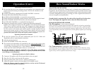
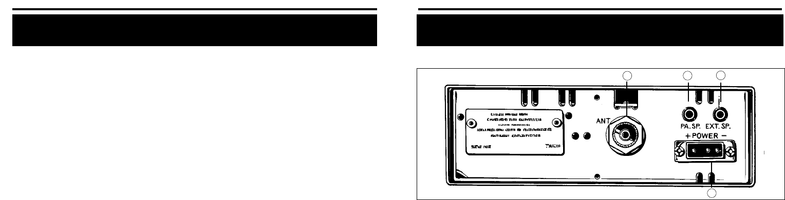
C. Rear Panel
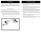
1. PUBLIC ADDRESS: An external 8-ohm 4.0 watt PA speaker may be connect-
ed to the PA Speaker Jack when this unit is used as a public address system.
The speaker should be directed away from the microphone to prevent acoustic
feed-back. Physical separation or isolation of the microphone and speaker
must be employed when operating the PA at high output levels.
2. EXTERNAL SPEAKER: The External Speaker Jack is used for remote receiver
monitoring. The external speaker should have 8-ohm impedance and be rated
to handle at least 4.0 watts. When the external speaker is plugged in, the inter-
nal speaker is automatically disconnected.
3. ANTENNA CONNECTOR: This SO-239 connector permits connection of the
transmission line cable PL-259 connector to the transceiver.
4. POWER. This jack permits connection of the DC power to the transceiver. A
power cord with polarized plug is supplied with the radio. The polarized plug
ensures that the power will always be connected properly.
1
2
3
4
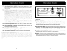
13. CH.19/CH.9/NORMAL SWITCH. Used for instant selection of emer-
gency Channel 9 (CH. 9 position) or information Channel 19. In NOR-
MAL position, all 40 CB channels are selected by the CHANNEL SELEC-
TOR switch (8).
14. S-METER. Swings proportionally to the strength of the incoming signal
during receiving. The S/RF-SWR-CAL switch must be in the S/RF position.
RF-METER.Swings proportionally to the RF output power while trans-
mitting. The S/RF-SWR-CAL switch must be in the S/RF position.
SWR METER. Measures standing wave ratio of the antenna system.
Used to properly adjust the length of the antenna and to monitor the
quality of the coaxial cable and all RF electrical connections. If there is any
degradation whatsoever in any of the foregoing, due to humidity, salt
spray, vibration or corrosion, the SWR meter reading will rise, thereby
indicating that a problem exists.
To calibrate, switch to the "CAL" position, transmit by pressing the mike
switch, and adjust the SWR control to the "CAL" mark on the meter; then
switch to "SWR" position for the SWR measurement.
15. RX/TX LED INDICATOR. When your radio is in the CB receive mode,
the LED will be green. When in transmit mode, the LED will be red.
16. SOUNDTRACKER™ SWITCH. Depressing this button turns on the
SoundTracker system in your CB.
17. SOUNDTRACKER™ INDICATOR. A red LED will illuminate when the
SoundTracker system is engaged on your CB.
18. LED CHANNEL DISPLAY. The selected channel will be displayed.
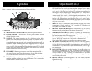
B. PRESS-TO-TALK MICROPHONE. Both the receiver and transmitter are con-
trolled by the Press-to-Talk switch on the microphone. Press the switch and the
transmitter is activated; release the switch to receive. When transmitting, hold the
microphone two inches from the mouth and speak clearly in a normal voice. The
microphone provided with your radio is a detachable low-impedance dynamic
type.
Operation (Cont.)
10