


1-3
Cisco ASR 1000 Series Aggregation Services Routers SIP and SPA Hardware Installation Guide
OL-14126-15
Chapter 1 Overview: Cisco ASR 1000 Series Aggregation Services Routers SIPs
SPA Interface Addresses on SIPs
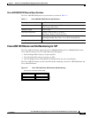
SPA Interface Addresses on SIPs
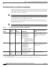
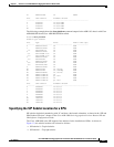
Interface addresses specify the physical location of each interface on a router or switch. Table 1-3
describes how to identify the interface addresses for SPAs supported on the SIPs.
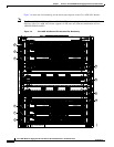
Identifying Slots and Subslots for SIPs and SPAs
This section describes how to specify the physical locations of a SIP and SPA on the Cisco ASR 1000
Series Routers within the command-line interface (CLI) to configure or monitor the devices.
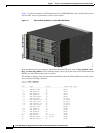
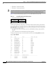
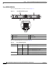
Specifying the Slot Location for a SIP
The Cisco ASR 1000 Series Routers support different chassis models, each of which supports a certain
number of chassis slots.
• The Cisco ASR 1013 Router supports six chassis slots for SIPs.
• The Cisco ASR 1006 Router supports three chassis slots for SIPs.
• The Cisco ASR 1004 Router supports two chassis slots for SIPs.
• The Cisco ASR 1002 Router and Cisco ASR 1002-X Router support one chassis slot for a SIP that
is permanently installed, and the integrated Route Processor and Gigabit Ethernet ports reside in
SPA subslot 0.
Table 1-3 SPA Interface Addresses
SIP Address Format Description
Cisco ASR 1000 Series SIP router-module-slot/SIP-subslot/SPA-port-number Router module slot—0 through 2
SIP subslot—0 through 3
SPA port number—0 through x
Note The maximum number of SPA
ports depends on the type of
SPA.