


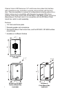
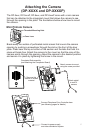
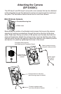
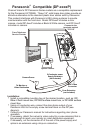
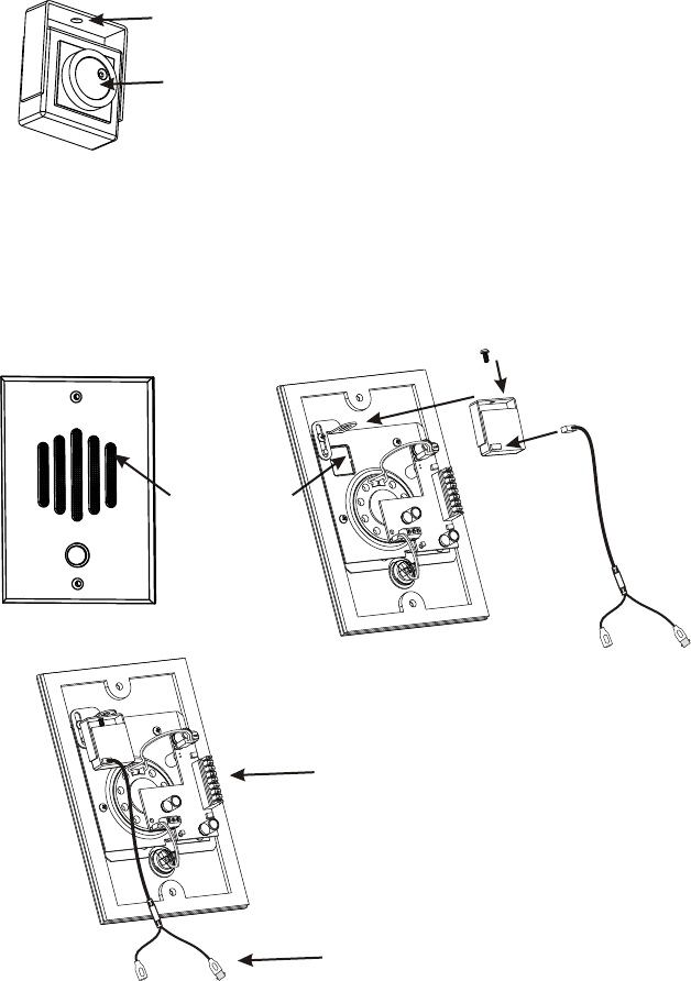
The DP-5xxxC and DP-6xxxC come with a mini camera that can be attached
to the integrated mount that allows the camera to see through the opening in
the plate. The illustrations bellow show how to mount the camera.
Attaching the Camera
(DP-XXXXC)
Mini Pinhole Camera
Threaded Mounting Hole
Cone Lens
Connect Intercom Hub here
(see following pages for details)
Connect to power supply
and video distribution system
Remove this
section of screen
material
Attach camera to mount
using the screw provided
Attach pigtail
to rear of
camera
Completed Sub-assembly
(see Attaching the Companion Board)
Break away the section of perforated metal screen that covers the camera
opening by pushing a screwdriver through the slot on the front of the door
plate. Press near the top or bottom of the section and the tabs that hold it in
place will break free. Attach the camera to the mount so that the cone of the
camera points through the opening. Adjust the camera to the desired position
and secure it in place by tightening the screw in the mount.
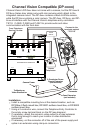
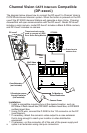
This door intercom product consists of two sub assemblies which must be
attached to each other before the final assembly can be installed. In this
guide the electronic sub assembly will be referred to as the “Companion
Board” and the mechanical assembly will be referred to as the “Door Plate.”
Review the following diagrams and assemble as shown.
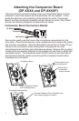
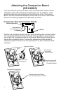
Attaching the Companion Board
(DP-XXXXC)
Companion Board Connection Details
To Speaker
Microphone
(attached to back side)
Volume Adjustment
Companion Board
Microphone
Tube
Connect Intercom Hub here
(see following pages for details)
Bend mounting tabs
over to secure the
Companion Board
Completed Sub-assembly
Attach button
and speaker
wires as shown
Align holes with
mounting tabs
Position the companion board onto the three mounting tabs as shown below.
The microphone attached to the back side of the companion board should
line up with the microphone tube on the bracket. Bend the mounting tabs to
secure the companion board. Connect the speaker and button wires by
sliding the small connector over the exposed pins on the companion board
as shown.
To Button
6
7