


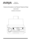

Avaya Inc.
Installation and Operation
Model EA20R
Page 6
Installing the EA20R
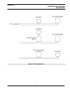
Note: The EA20R must be connected to the tip and ring conductors
associated with the telephone for which the additional alerting signal
is required. The connection may be made either before or after the
telephone or it may branch off from a junction box.
See: Figure 3 - Wiring
Alternatives
• Declassify the hazardous location before proceeding with any
installation or electrical wiring.
WARNING
Do not connect this device to any power source other than telephone tip
and ring, doing so will destroy the circuitry and void the warranty.
Caution: Installation or
electrical wiring in a
hazardous location
could result in serious
injury to personnel or
damage to property.
• Follow all appropriate electrical codes and use only approved electrical
fittings for the installation.
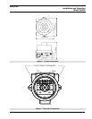
• Choose a wall location that is free of obstructions and permits space for ½”
NPT conduit runs.
See: Figure 1 - Overall
Dimensions
• Ensure mounting can support 5 lbs (2.3 kgs) and any additional anticipated
load.
• Ensure that none of the electrical connection circuits are live.
• Secure the unit using screws or bolts through the mounting tabs.
• Remove the screw cover.
Tip: Use #8 or M4
screws or equivalent
bolts to secure the unit to
the wall.
• Run tip and ring wiring to the unit using appropriate electrical fittings.
• Attach the telephone tip and ring leads to the terminal strip.
See: Figure 2 - Electrical
Connections
• Replace the screw cover ensuring that the faces of the cover and the
enclosure are in contact.
• Apply power to the system.
• Test the unit by calling from another unit on the exchange.
Maintenance
• Declassify the hazardous location or disconnect the line before
proceeding with any maintenance or repairs.
• To maintain hazardous area compliance the only field repair permitted is the
replacement of the driver assembly. All other repairs or alterations must be
carried out by Avaya or an Authorized Service Depot. See Warranty and
Disclaimer for details.
• When replacing the screw cover ensure that the faces of the cover and the
enclosure are in contact.