


Page 54 - Port Pinouts Technical Data
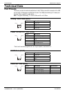
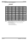
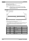
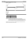
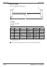
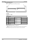
WAN Port (37 Way D-Type Socket)
Pin 1
Pin 37
Pin No. Description Signal Dir. Pin No. Description Signal Dir.
1 V11 Rx-B
Í
20 V11 Rx-A
Í
2 V11 Ind-A
Í
21 V11 Ind-B
Í
3 V11 Clk-A
Í
22 V11 Clk-B
Í
4 V11 Tx-A
Î
23 V11 Tx-B
Î
5 V11 Ctl-B
Î
24 V11 Ctl-A
Î
6 V11 Gnd 25 WAN ID 0
Í
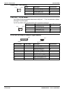
7 WAN ID 1
Í
26 V24 Tx
Î
8 V24 DTR
Î
27 V24 RTS
Î
9 V24 Rx
Í
28 V24 RxClk
Í
10 V24 TxClk
Í
29 V24 RI
Í
11 V24 DCD
Í
30 V24 DSR
Í
12 V24 CTS
Í
31 N/C
13 N/C 32 V35 Tx-A
Î
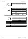
14 V35 Tx-B
Î
33 V35 SCTE-A
Î
15 V35 SCTE-B
Î
34 V35 Gnd
16 V35 Rx-B
Î
35 V35 Rx-A
Î
17 V35 TxClk-B
Í
36 V35 TxClk-A
Í
18 V35 RxClk-B
Í
37 V35 RxClk-A
Í
19 CHASSIS
Notes: 1. For the USA, only FCC Part 68 registered data circuit terminal equipment should be
connected to the WAN Ports.
2. * For X21, V24/28 and V35 variants, pins 7 and 25 are connected as follows:
X21: Pin 7 is connected to pin 6
V24/28: Pin 25 is connected to pin 6
V35: Pins 7 and 25 are connected to pin 6
Page 54 - Technical Data IP Office Installation Manual
Port Pinouts 40DHB0002USCL – Issue 7 (09/25/2002)