


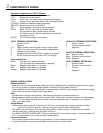

Individual Components for LEF-3L System:
LEF-3L 3-call master with selective door release
LE-D Surface mount door station
LE-DA Flush mount door station with stainless steel faceplate
LE-DL Surface mount metal door station with illuminated directory
LS-NVP/B Vandal and weather resistant sub station
SBX-NVP Surface mount box for LS-NVP/B
SA-1 Surge Arrestor (1 per 2 wires being protected)
RY-PA Relay, 12V DC input, N/O dry closure output.
One required for each contact closure required
off of each channel. Can be momentary or maintained,
according to wiring.
PS-12C 12V DC power supply, 1 per system
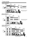
LEF-3L TERMINAL DEFINITIONS:
+ Positive 12V DC
- Negative
1~3 Station number, communication to sub or other master
C "CALL", for receiving a call from another master station
E Common communication
R Occupied light control (0V DC when system is occupied)
Y All Call override control (Not used in LEF-3L system)
Color-coded Wires:
White Common Door release activation
(12V DC when door release button is pressed)
Brown Negative when station 1 is pressed
Red Negative when station 2 is pressed
Orange Negative when station 3 is pressed
WIRING & INSTALLATION:
Before Installation:
· Make sure you have the proper power supply(ies) and all necessary and compatible equipment for the system.
· Lay out your system in advance, assigning station numbers for all sub station locations.
· Surge protection for the intercom equipment is recommended. Add SA-1 surge arrestors for the power supply,
plus one per two wires connected to the master station.
Wire:
· Shielded wire is strongly recommended. Use the proper gauge for the distance being run.
· Wiring between masters must be a multi-conductor cable. If more than one cable is used to connect masters,
the "E", "C", and number terminal wires must be in the same jacketed cable. If necessary, run multiple "E"
wires, one in each cable.
Wiring Method:
· Run intercom cables at least 20" away from all AC wiring, fluorescent lights, dimmer switches, and other
electrical or electronic devices. Intercom wiring can cross AC wires at 90 degrees.
· Sub stations can be homerun to the nearest master station, or daisy-chained. If daisy-chained, include 2
common wires plus 1 individual wire per station on the run.
· In a SINGLE MASTER SYSTEM ONLY: Subs can be wired with 2 conductors homerun. Jumpers between "E"
and "-" must be attached on all subs and at the master station.
Intercom Locations:
· Do not install intercoms near dimmer or light switches, or other electrical wall devices.
· To prevent feedback, do not place sub stations back-to-back on a common wall.
Pg. 2
2 COMPONENTS & WIRING
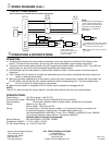
LE-D/LE-DA TERMINAL DEFINITIONS:
1 Station number
E Common communication
- Negative
LS-NVP/B TERMINAL DEFINITIONS:
Red Station number
Black Common communication
Green Negative
LE-DL TERMINAL DEFINITIONS:
1 Station number
E Common communication
+ Positive
- Negative