


Pg. 2
TC-MD Instr.
0205js
Toll Free Technical Support
Phone: 1-800-692-0200
FAX: 1-800-832-3765
E-mail: tech-serv@aiphone.com
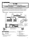
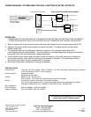
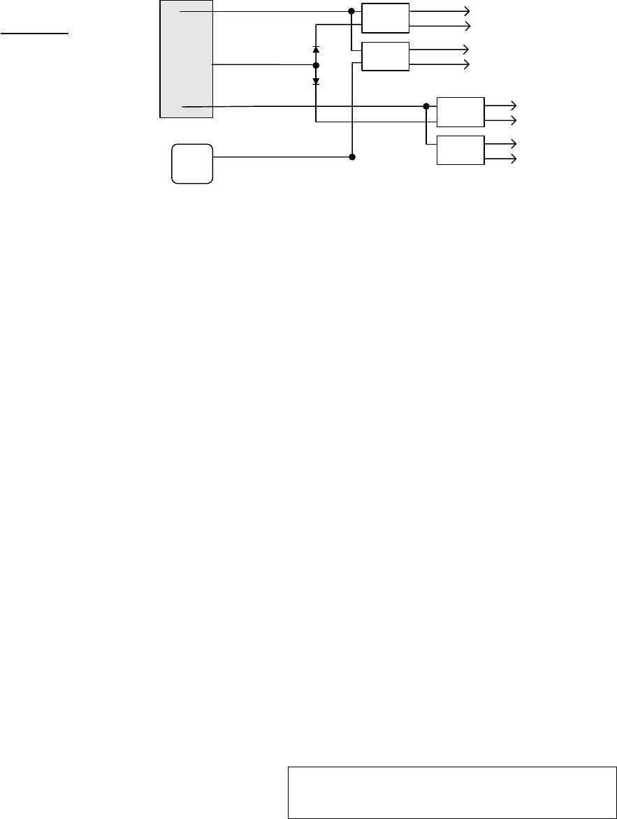
WIRING DIAGRAM: SYSTEM USED FOR DUAL FUNCTION OF EXTRA CONTACTS
Aiphone Communication Systems
1700 130th Ave. N.E.
Bellevue, WA 98005
(425) 455-0510
FAX (425) 455-0071
OPERATION:
* POWER SWITCH ON THE BACK OF THE MASTER MUST BE ON FOR SYSTEM TO BE OPERABLE.
** DOOR RELEASE BUTTON IS LOCATED BELOW THE "TRANSFER" BUTTON ON THE MASTER.
1. When a station calls in, pick up the handset and press the selector button corresponding to the lit LED.
2. Speak to the person at the remote station through the handset. The person at the remote station
speaks hands free.
3. To release the door at the calling party's location, press the "door release" button while still in
communication with the calling station. This will activate the corresponding relay as long as the button is
being held, which will activate the door release mechanism.
4. If both selective door release and a constant closure are used on a channel, the device connected to
the "constant closure" relay will be on as long as the channel is selected. The "momentary closure"
will only be active when the door release button is pressed.
5. When the conversation is completed, hang up the handset.
SPECIFICATIONS
Power Source: 18V DC or 16V AC at master. Use PS-1820UL or 16V AC Transformer (Not supplied by Aiphone)
or AC Transformer (16V AC, 10VA or greater).
Communication: Handset at master
Hands free at sub station
Calling: Master to sub: By voice only.
Sub to master: Call button on sub activates tone and LED at master
Wiring: 2 conductors homerun from door to door station adaptor.
Four (4) common wires plus one (1) individual wire per station from door adaptor to Master.
Use Aiphone #812202 (2 cond., 22AWG) or #812206 (6 cond., 22AWG) wire.
Wiring Distance:
Door to Adaptor: 500' with 22AWG; 1,200' with 18AWG.
Adaptor to Master: 210' with 22AWG; 495' with 18AWG.
For additional information about this system,
please refer to the TC-M instructions.
1
L
2
RY-PA
#1
BLK
12+
12-
RY-PA
#2
In TC-MD Master
RY-PA
#1
RY-PA
#2
BLK
BLK
BLK
YEL
Momentary closure #1
YEL
Constant closure #1
YEL
Momentary
closure #2
YEL
Constant
closure #2
Equipment for each station that requires
both a constant closure and momentary
closure when a channel is selected:
2 RY-PA relays
1 Diode (1N4001)
DUAL FUNCTIONS FROM EACH CHANNEL:
Terminal Block Inside Master