


Page 2
WIRING DIAGRAMS (cont):
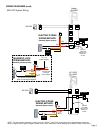
KB & KC System Wiring
1A1
1A2
Master
KB-3MRD
B1
B2
2A1
2A2
3A1
3A2
CN11
Org
Yel
+
-
PS-2420UL
+
-
A2
KB-DAR
A1
LOCK
POWER
Red
Blk
Brn
Org
Yel
ELECTRIC STRIKE
WIRING METHOD:
(Normally Open contact)
Connect
YELLOW
wire of CN11
directly to +
on unit.
Red
Blk
Brn
Org
Yel
COM
N/C
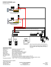
MAGNETIC LOCK
WIRING METHOD:
(Normally Closed contact)
Use Brown & Yellow wires
when connecting to Maglock.
LOCK
POWER
To (-) of
power supply
Connect Red
to Orange
lead of Master
+
-
+
-
LOCK
POWER
KC-DAR
A1
A2
PS-2420UL
+
-
1A1
1A2
KC-1GRD
KC-1MRD
B2
+
-
S
S
B1
Red
Blk
Brn
Org
Yel
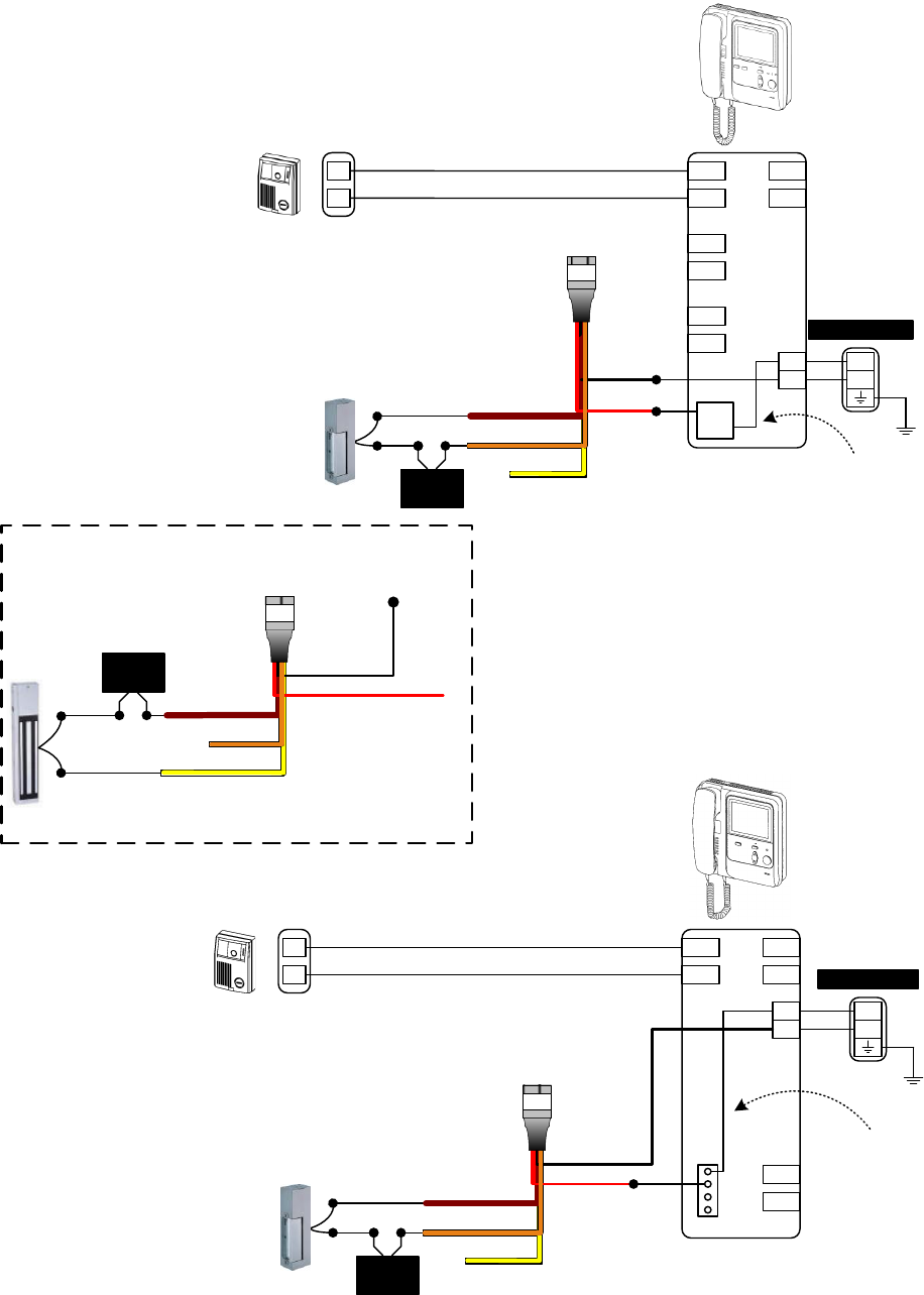
ELECTRIC STRIKE
WIRING METHOD:
(Normally Open contact)
Connect
YELLOW
wire of CN11
directly to +
on unit.
Yel
Org
COM
N/O
NOTE: The door release contacts are rated at 12V AC, 400mA. The RY-24L should be used in any application where the
strike or maglock has a higher voltage or draws more current. Otherwise, internal damage to the KB/KC monitor could result.