WIRING DIAGRAMS - CONT.
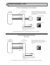
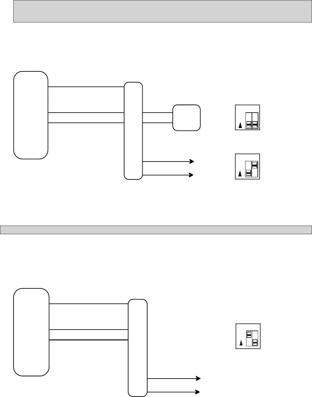
TD-H/Z TELEPHONE TYPE SYSTEM
MICROPROCESSOR SYSTEMS
(RCX, YKX)
PS-12C
7
8
9
MC-A
The TD-H and TD-Z system uses either
the built-in PD-1 (Standard) or the PD-2
(Talkback) adaptors by setting switches 7
& 8 as follows:
GND
4
4
5
to 70V speakers
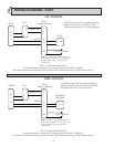
When paging from a microprocessor
based system (RCX, YKX), use the built-in
MC-A adaptor. Set switches 7 & 8 as
follows:
78
ON
For each paging zone required, use the appropriate sized PG-C amplifier.
78
ON
78
ON
For each paging zone (up to a total of four), use the appropriate sized PG-C amplifier.
Terminal #
(–)
+
–
7
9
TB1
8
+12VDC
(+)
(–)
12 VDC
TD-H/Z
PG-nC
Paging Amplifier
PD-1 (Standard)
PD-2 (Talkback)
Note: To prevent any possible oscillation,
ensure that the speaker wires are kept away
from any input wiring connected to the
terminal strip .
Note: To prevent any possible oscillation,
ensure that the speaker wires are kept away
from any input wiring connected to the
terminal strip .
TB1
P1
GND
+
Central
Exchange Unit
PG-nC
Paging Amplifier
+24VDC
Page C/2
Page C/2
to 70V speakers


