


OPERATION:
1. The entry station has multiple call buttons with an associated directory card. Press the button of the person you
wish to call.
2. LEF and LEM master station(s) will ring an electronic call tone as long as the call button on the entrance station is
being held. The C-ML/A master(s) will ring a four stroke chime.
3. To answer, select the station button with the lit LED. If the LED has gone out (after approx. 20 seconds), press
the selector button assigned to the entry station (LEF only).
4. Person at the inside station presses TALK button to talk, and releases to listen. Person at the entry station speaks
hands free.
5. When finished with the call, press the OFF button on the master station (LEF and LEM-1DL/C only). The C-ML/A
master will time out after approximately 20 seconds after the talk button is pressed.
6. On LEF and LEM-1DL/C sytems, if the "Occupied" lamp is on, the system is in use. Wait until LED goes out, or
determine if a master station has been left on unintentionally.
SPECIFICATIONS:
Power Source: Provided from master station. Use the appropriate power supply for the system:
1 PS-1225UL per system with LEF
1 PT-1210N for each LEM-1DL/C
1 SKK-620 for each C-ML/A
Impedance: 20 ohms
Communication: Hands free at entry station/Push-to-Talk at master station
Calling: LEF: Momentary call tone and LED, remaining lit for approx. 20 seconds
LEM-1DL/C: Momentary call tone
C-ML/A: 4 Stroke Chime
Wiring: LEF: 4 common (E, R, +, -) plus 1 individual per sub, looped; or 5 conductors homerun to each
master. Shielded cable is recommended.
Use Aiphone #822206 for homerun wiring or LE-B2, #822210 for LE-B4 & LE-B6,
or #822215 for LE-B10.
LEM-1DL/C and C-ML/A: 2 wires homerun to each master. Shielded cable is recommended.
Use Aiphone #822202.
Wiring Distance: 650' with 22AWG; 1,600' with 18AWG.
Dimensions (HxWxD): Flush mounted: 10-1/4" x 7-5/16" x 2-5/8" (flush depth)
Surface mounted: 10-3/8" x 7-1/2" x 2-1/16"
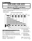
WIRING DIAGRAM:
LE-B4 WITH LEM-1DL/C MASTER STATIONS
Install
jumper
on E/-
Pg. 2
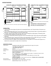
LE-B2 WITH C-ML/A MASTER STATIONS
NOTE:
Terminal definitions are sideways when looking at the
C-ML/A right side up. 1 and E terminals are on the
right column. + and - terminals are on the left column.
Two L terminals are on the top, right and left.
E
-
+
1
L
L
C-ML/A
LE-B2
E
-
1
2
E
-
+
1
L
L
SKK-620
C-ML/A
-
+
SKK-620
-
+
~
~
AC Power
Door Strike
C-ML/A: Use SKK-620 (6V DC) to power each master separately.
E
-
+
R
1
EL
EL
LEM-1DL/C
LE-B4
E
-
1
2
3
4
E
-
+
R
1
EL
EL
E
-
+
R
1
EL
EL
PT-1210N
LEM-1DL/C LEM-1DL/C
~
~
PT-
1210N
~
~
PT-
1210N
~
~
~
~
AC Power
Door Strike
LEM-1DL/C: Use 12-16V AC or 12-24V DC to power each master separately.