


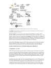

Example Three: Very similar to Example Two, except that the External NAT Port, Internal NAT Port, and
the port for the NAT PassThru Range are all located on the same physical port, by using sub−interfaces on
this physical port.
EXAMPLE ONE
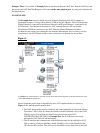
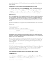
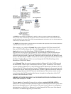
The Example One network, which was used in the development of the NAT software at
Compatible Systems, is using a MicroRouter 2220R as the NAT Router. The NAT Router has
IP port Ethernet 0 connected to the External Network and IP port Ethernet 1 connected to the
NAT Network. Two Macintosh workstations, a PC running Windows NT and another
MicroRouter 2220R are connected to the NAT Network Internal Ethernet hub. Other
workstations and routers are connected to the External Ethernet hub, but, for clarity, only the
connections to the NAT Router and the router connected to the Internet are shown here.
Figure 1
(*) NOTES: All of the machines in the NAT network must address their IP packets to the Internal Interface of the
"NAT" MR 2220 Router (Ethernet 1).
Several important points about Compatible Systems NAT implementation are shown in
Figure 1, and warrant special mention here:
The NAT functionality must be enabled in the router intended to do Network Address
Translation. This is done by setting the Enabled variable (Enabled = On) in the [NAT
Global] section. This will be described in more detail later in the NAT
CONFIGURATION SECTION. In Example One, the NAT Router is the router
between the NAT Network and the Internet.
1.
The IP interface that communicates with the Internet must also be enabled for NAT.
This is done by setting the NatMap variable (NatMap = On) on this interface in the
[IP <Section ID>] section. This will also be described in more detail later in the NAT
2.