


280-7323-00
5 DMX5555z 6 DMX5555z DMX5555z 7
4. NOMENCLATURE
Note:
• Be sure to read this chapter referring to the front diagrams of chapter “3. CONTROLS” on page 5 (unfold).
3.
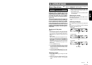
CONTROLS / LES COMMANDES / CONTROLES
Source unit / Appareil pilote / Unidad fuente
Note: Be sure to unfold this page and refer to the front diagrams as you read each chapter.
Remarque: Veuillez déplier cette page et vous référer aux schémas quand vous lisez chaque chapitre.
Nota: Cuando lea los capítulos, despliegue esta página y consulte los diagramas.
Display / Afficheur / Visualizador
1 Preset buttons (1 to 6)
Direct buttons (1 to 6) (7 to 12)
2 Z-EHCR (z-enhancer) button
3 DISP (display) button
4 SPE-ANA (spectrum analyzer) button
5 SCN (scan) button
PS/AS (preset scan/auto store) button
6 RPT (repeat) button
7 POWER button
FUNC (function) button
8 RDM (random) button
9 ISR (instant station recall) button
0 MUTE button
! BAND (band) button
TOP button
1 CD IN indication
2 SINGLE indication
3 ST (stereo) indication
4 SCN (scan) indication
5 RPT (repeat) indication
6 RDM (random) indication
7 Operation status indication
∗ The frequency, play time, clock, etc. are
displayed.
8 CD/MD changer indication
9 Title scroll indication
0 MD IN indication
! MANU (manual) indication
@ LD (loudness) indication
# A-M (audio mode) indication
$ Function mode indication
∗ The names of modes being selected, etc. are
displayed.
% Preset channel indication (1 to 6)
Disc number indication (1 to 12)
∗ The disc numbers corresponding to the discs
in the CD or MD changer light.
¥ Z-EHCR (z-enhancer) indication
& DISC indication
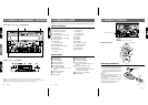
Names of Buttons
™
¡)
3
45678 9 0 !@#$%* ¥&(
1
123456 7 89 0
&
¥
%$# @!
@ ENT (enter) button
Play/pause button
# TITLE button
ADJ (adjust) button
$ MD EJECT button
% Left button
¥ Right button
& Up button
* Down button
( A-M (audio mode) button
LOUD (loudness) button
) CD EJECT button
¡ CD insertion slot
™ MD insertion slot
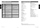
Display Items
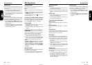
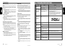
Inserting the Batteries
1. Turn the remote control unit over, then slide
the rear cover in the direction of the arrow.
2. Insert the AA (UM-3/1.5V) batteries that came
with the remote control unit facing in the di-
rections shown in the figure, then close the
rear cover.
Notes:
Using batteries improperly can cause them to ex-
plode. Take note of the following points:
• When replacing batteries, replace both batteries
with new ones.
• Do not short-circuit, disassemble or heat batter-
ies.
• Do not dispose of batteries into fire or water.
• Dispose of spent batteries properly.
5. REMOTE CONTROL
Remote control unit
Receiver for remote control unit
Signal transmitter
Operating range: 30° in all directions
£
;
ª
⁄
•
¤
¶
§
¢
º
‹
Rear side
AA (UM-3/1.5V)
Batteries
Rear cover
2