


SW-2
SW-2
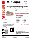
Vandal Resistant
Momentary DPDT Push
Button Switch
September 29, 1999
Now you can add the convenience of a Double Pole
Double Throw momentary switch to selected Viking
products.
This is an ideal solution for triggering doorbells, video
cameras, recorders, lights, etc. whenever the handsfree
phone is accessed.
If a timed contact closure is needed, use a Viking TDR-1
along with the SW-2 (Fax Back Document 421).
Add a Second Set of Momentary Contacts
to Your Viking Handsfree Phone
P
P
h
h
o
o
n
n
e
e
.
.
.
.
.
.
7
7
1
1
5
5
.
.
3
3
8
8
6
6
.
.
8
8
8
8
6
6
1
1
i
i
n
n
f
f
o
o
@
@
v
v
i
i
k
k
i
i
n
n
g
g
e
e
l
l
e
e
c
c
t
t
r
r
o
o
n
n
i
i
c
c
s
s
.
.
c
c
o
o
m
m
h
h
t
t
t
t
p
p
:
:
/
/
/
/
w
w
w
w
w
w
.
.
v
v
i
i
k
k
i
i
n
n
g
g
e
e
l
l
e
e
c
c
t
t
r
r
o
o
n
n
i
i
c
c
s
s
.
.
c
c
o
o
m
m
1. Disconnect the (2) wires from the SPST switch.
2. Remove the hex nut and the SPST switch from
the handsfree phone.
3. Install the SW-2 switch in the reverse order.
4. Solder the existing switch wires to the common (C)
and the normally open (NO) contacts of the SW-2.
5. Solder your circuit to be triggered (doorbell, light,
camera, etc.) to the unused second set of NO or
NC contacts.
Add Double Pole, Double Throw contacts to the fol-
lowing Viking products:
• E-1600
• E-1600A
• E-1600-02
• E-1600-02A
• E-1600-40
• E-1600-40A
• E-1600-45
• E-1600-45A
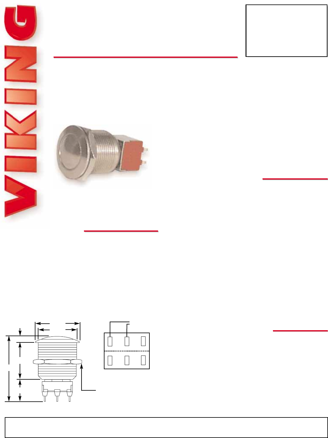
Dimensions: 22mm diameter x 38mm (0.87” diameter x 1.5”)
Shipping Weight: 0.45 kg (1 lb)
Environmental: -30° C to 85° C (-22° F to 185° F) with 5% to
95% non-condensing humidity
Circuit: DPDT (Double Pole Double Throw)
Closure Type: Momentary
Maximum Current/Voltage Rating with a Resistive Load: 7A
30VDC, 6A 125VAC, 3A 250VAC
Termination: Solder lugs
Electrical Life: 60,000 cycles at full load
P
P
r
r
a
a
c
c
t
t
i
i
c
c
e
e
T
T
E
E
L
L
E
E
C
C
O
O
M
M
S
S
O
O
L
L
U
U
T
T
I
I
O
O
N
N
S
S
F
F
O
O
R
R
T
T
H
H
E
E
2
2
1
1
S
S
T
T
C
C
E
E
N
N
T
T
U
U
R
R
Y
Y
TECHNICAL
TECHNICAL
A
A
p
p
p
p
l
l
i
i
c
c
a
a
t
t
i
i
o
o
n
n
s
s
I
I
n
n
s
s
t
t
a
a
l
l
l
l
a
a
t
t
i
i
o
o
n
n
S
S
p
p
e
e
c
c
i
i
f
f
i
i
c
c
a
a
t
t
i
i
o
o
n
n
s
s
Due to the dynamic nature of the product design, the information contained in this document is subject to change without notice. Viking Electronics, and its affiliates and/or
subsidiaries assume no responsibility for errors and omissions contained in this information. Revisions of this document or new editions of it may be issued to incorporate
such changes.
Fax Back Doc 844 ZF301420 Rev APrinted in the U.S.A.
P
P
r
r
o
o
d
d
u
u
c
c
t
t
S
S
u
u
p
p
p
p
o
o
r
r
t
t
L
L
i
i
n
n
e
e
.
.
.
.
.
.
7
7
1
1
5
5
.
.
3
3
8
8
6
6
.
.
8
8
6
6
6
6
6
6
F
F
a
a
x
x
B
B
a
a
c
c
k
k
L
L
i
i
n
n
e
e
.
.
.
.
.
.
7
7
1
1
5
5
.
.
3
3
8
8
6
6
.
.
4
4
3
3
4
4
5
5
C
NO
NC
0.866”
0.748”
0.742”
0.633”
1.50”
0.134”
Hex Nut
0.748”
(across flats)
• E-1600-50
• E-1600-50A
• E-1600-BLT
• K-1500-EHF
• K-1600-EHF
• K-1600-EHFA
• W-3000
• K-1700-3
C
C
NO
NO
NC
NC
To Existing
Switch Wires
View of contacts available
on the SW-2