


r
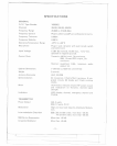
GENERAL
F.C.C. Type Number
Channels
Frequency Range
Frequency Control
Frequency Tolerance
Frequency Stability
Operating Temperature Range
Microphone
Input Voltage
Current Drain
Cabinet Dimensions
Weight
Antenna Connector
Semiconductors
Meter
Indicators
I
. .1
I
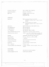
TRANSMITTER
Power Output
Modulation
Intermodulation Distortion
SSB Carrier Suppression
Unwanted Sideband
- ..{.
-
=-- ---=
SPECIFICATIONS
1005002
40AM, 40LSB, 40USB
26.965 to 27.405 MHz
Phase Locked Loop(PLL) synthesized circuitry.
0.005%
0.001%
-20°C to +50°C
Plug-in type; dynamic with push-to-talk switch
and coiled cord.
13.8V DC nominal, 15.9V max., 11.7V
min.
(positive or negative ground).
Transmit: AM full mod., 3A maximum.
SSB, 12 watts PEP output, 3A
maximum.
Receiver: squelched; 0.5A, maximum audio
output 1A.
7-7/8"(W) x 2-3/8"(H) x 9-1/4"(D)
5 pounds
UHF, SO-239
44 transistors, 3 field effect transistors, 6 inte-
grated circuits, 62 diodes and 3 light emitting
diodes.
Illuminated; indicates relative RF power output
and modulation on Transmit, received signal
strength.
LED display; channel, emergency channel and
TX/RX.
AM,4 watts
SSB, 12 watts, P.E.P.
High and Iow level Class B, Amplitude Modula-
tion.
SSB: 3rd and 5th order, more than -25 dB.
7th and 9th order, more than -35 dB.
More than -45 dB.
More than -45 dB.
-9-
..----..---.
r
i
--
-~