


Rev. 0.5 43
C8051F340/1/2/3/4/5/6/7
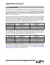
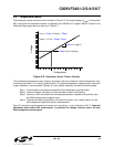
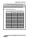
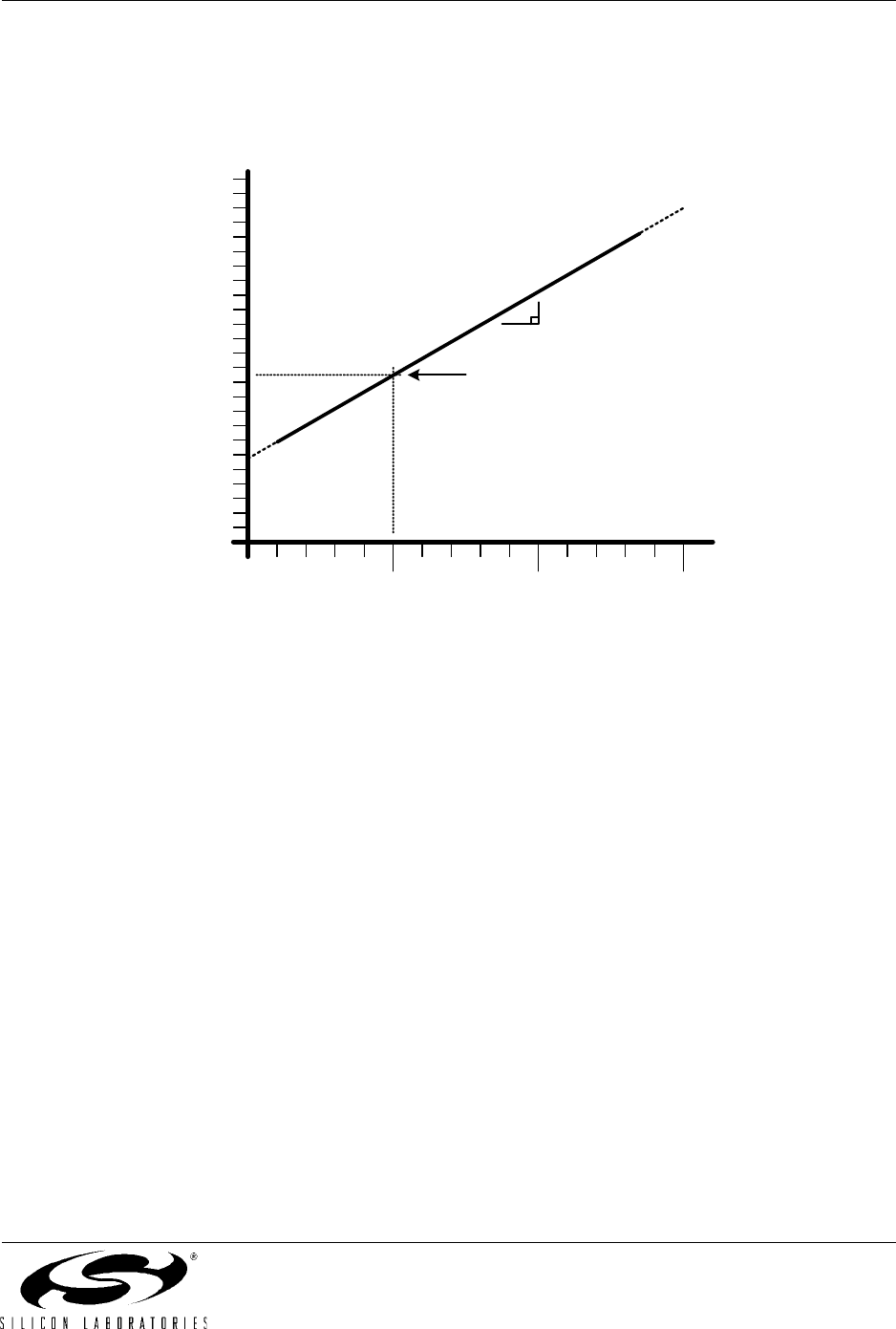
5.2. Temperature Sensor
The temperature sensor transfer function is shown in Figure 5.2. The output voltage (V
TEMP
) is the positive
ADC input when the temperature sensor is selected by bits AMX0P4-0 in register AMX0P. Values for the
Offset and Slope parameters can be found in
Table 5.1.
Figure 5.2. Temperature Sensor Transfer Function
The uncalibrated temperature sensor output is extremely linear and suitable for relative temperature mea-
surements (see Table 5.1 for linearity specifications). For absolute temperature measurements, offset and/
or gain calibration is recommended. Typically a 1-point (offset) calibration includes the following steps:
Step 1. Control/measure the ambient temperature (this temperature must be known).
Step 2. Power the device, and delay for a few seconds to allow for self-heating.
Step 3. Perform an ADC conversion with the temperature sensor selected as the positive input
and GND selected as the negative input.
Step 4. Calculate the offset characteristics, and store this value in non-volatile memory for use
with subsequent temperature sensor measurements.
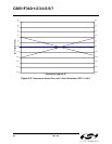
Figure 5.3 shows the typical temperature sensor error assuming a 1-point calibration at 25 °C. Note that
parameters which affect ADC measurement, in particular the voltage reference value, will also
affect temperature measurement.
Temperature
Voltage
V
TEMP
= (Slope x Temp
C
) + Offset
Offset (V at 0 Celsius)
Slope (V / deg C)
Temp
C
= (V
TEMP
- Offset) / Slope