


C8051F340/1/2/3/4/5/6/7
274 Rev. 0.5
22.4. Register Descriptions for PCA
Following are detailed descriptions of the special function registers related to the operation of the PCA.
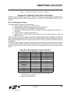
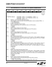
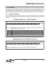
SFR Definition 22.1. PCA0CN: PCA Control
Bit7: CF: PCA Counter/Timer Overflow Flag.
Set by hardware when the PCA Counter/Timer overflows from 0xFFFF to 0x0000. When the
Counter/Timer Overflow (CF) interrupt is enabled, setting this bit causes the CPU to vector
to the PCA interrupt service routine. This bit is not automatically cleared by hardware and
must be cleared by software.
Bit6: CR: PCA Counter/Timer Run Control.
This bit enables/disables the PCA Counter/Timer.
0: PCA Counter/Timer disabled.
1: PCA Counter/Timer enabled.
Bit5: UNUSED. Read = 0b, Write = don't care.
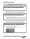
Bit4: CCF4: PCA Module 4 Capture/Compare Flag.
This bit is set by hardware when a match or capture occurs. When the CCF4 interrupt is
enabled, setting this bit causes the CPU to vector to the PCA interrupt service routine. This
bit is not automatically cleared by hardware and must be cleared by software.
Bit3: CCF3: PCA Module 3 Capture/Compare Flag.
This bit is set by hardware when a match or capture occurs. When the CCF3 interrupt is
enabled, setting this bit causes the CPU to vector to the PCA interrupt service routine. This
bit is not automatically cleared by hardware and must be cleared by software.
Bit2: CCF2: PCA Module 2 Capture/Compare Flag.
This bit is set by hardware when a match or capture occurs. When the CCF2 interrupt is
enabled, setting this bit causes the CPU to vector to the PCA interrupt service routine. This
bit is not automatically cleared by hardware and must be cleared by software.
Bit1: CCF1: PCA Module 1 Capture/Compare Flag.
This bit is set by hardware when a match or capture occurs. When the CCF1 interrupt is
enabled, setting this bit causes the CPU to vector to the PCA interrupt service routine. This
bit is not automatically cleared by hardware and must be cleared by software.
Bit0: CCF0: PCA Module 0 Capture/Compare Flag.
This bit is set by hardware when a match or capture occurs. When the CCF0 interrupt is
enabled, setting this bit causes the CPU to vector to the PCA interrupt service routine. This
bit is not automatically cleared by hardware and must be cleared by software.
R/W R/W R/W R/W R/W R/W R/W R/W Reset Value
CF CR - CCF4 CCF3 CCF2 CCF1 CCF0 00000000
Bit7 Bit6 Bit5 Bit4 Bit3 Bit2 Bit1 Bit0 SFR Address:
(bit addressable)
0xD8