


Rev. 0.5 95
C8051F340/1/2/3/4/5/6/7
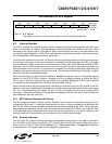
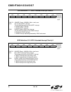
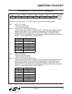
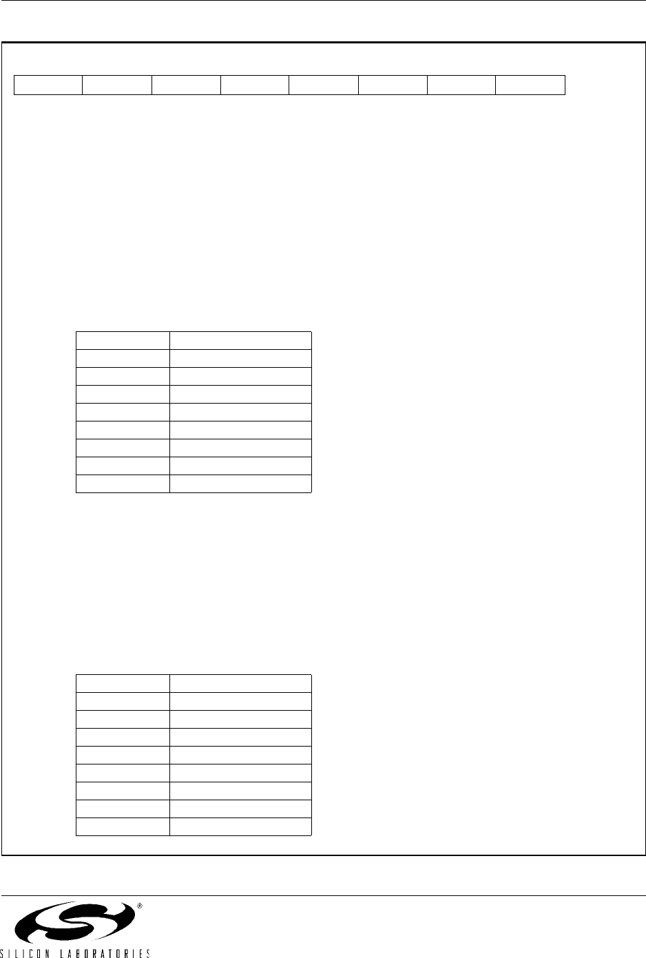
SFR Definition 9.13. IT01CF: INT0/INT1 Configuration
Bit7: IN1PL: /INT1 Polarity
0: /INT1 input is active low.
1: /INT1 input is active high.
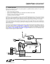
Bits6–4: IN1SL2–0: /INT1 Port Pin Selection Bits
These bits select which Port pin is assigned to /INT1. Note that this pin assignment is inde-
pendent of the Crossbar; /INT1 will monitor the assigned Port pin without disturbing the
peripheral that has been assigned the Port pin via the Crossbar. The Crossbar will not
assign the Port pin to a peripheral if it is configured to skip the selected pin (accomplished by
setting to ‘1’ the corresponding bit in register P0SKIP).
Bit3: IN0PL: /INT0 Polarity
0: /INT0 interrupt is active low.
1: /INT0 interrupt is active high.
Bits2–0: INT0SL2–0: /INT0 Port Pin Selection Bits
These bits select which Port pin is assigned to /INT0. Note that this pin assignment is inde-
pendent of the Crossbar. /INT0 will monitor the assigned Port pin without disturbing the
peripheral that has been assigned the Port pin via the Crossbar. The Crossbar will not
assign the Port pin to a peripheral if it is configured to skip the selected pin (accomplished by
setting to ‘1’ the corresponding bit in register P0SKIP).
R/W R/W R/W R/W R/W R/W R/W R/W Reset Value
IN1PL IN1SL2 IN1SL1 IN1SL0 IN0PL IN0SL2 IN0SL1 IN0SL0 00000001
Bit7 Bit6 Bit5 Bit4 Bit3 Bit2 Bit1 Bit0 SFR Address:
0xE4
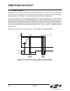
Note: Refer to SFR Definition 21.1 for INT0/1 edge- or level-sensitive interrupt selection.
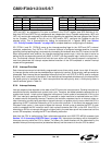
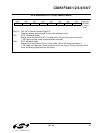
IN1SL2–0 /INT1 Port Pin
000 P0.0
001 P0.1
010 P0.2
011 P0.3
100 P0.4
101 P0.5
110 P0.6
111 P0.7
IN0SL2–0 /INT0 Port Pin
000 P0.0
001 P0.1
010 P0.2
011 P0.3
100 P0.4
101 P0.5
110 P0.6
111 P0.7