


Rev. 0.5 85
C8051F340/1/2/3/4/5/6/7
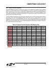
9.2.7. Register Descriptions
Following are descriptions of SFRs related to the operation of the CIP-51 System Controller. Reserved bits
should not be set to logic
l. Future product versions may use these bits to implement new features in which
case the reset value of the bit will be logic
0, selecting the feature's default state. Detailed descriptions of
the remaining SFRs are included in the sections of the datasheet associated with their corresponding sys
-
tem function.
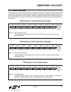
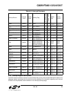
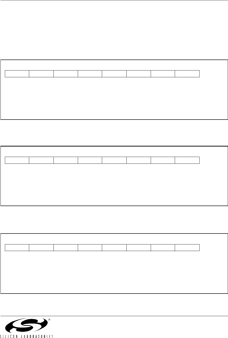
SFR Definition 9.1. DPL: Data Pointer Low Byte
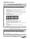
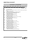
SFR Definition 9.2. DPH: Data Pointer High Byte
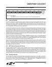
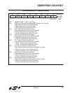
SFR Definition 9.3. SP: Stack Pointer
Bits7–0: DPL: Data Pointer Low.
The DPL register is the low byte of the 16-bit DPTR. DPTR is used to access indirectly
addressed memory.
R/W R/W R/W R/W R/W R/W R/W R/W Reset Value
00000000
Bit7 Bit6 Bit5 Bit4 Bit3 Bit2 Bit1 Bit0 SFR Address:
0x82
Bits7–0: DPH: Data Pointer High.
The DPH register is the high byte of the 16-bit DPTR. DPTR is used to access indirectly
addressed memory.
R/W R/W R/W R/W R/W R/W R/W R/W Reset Value
00000000
Bit7 Bit6 Bit5 Bit4 Bit3 Bit2 Bit1 Bit0 SFR Address:
0x83
Bits7–0: SP: Stack Pointer.
The Stack Pointer holds the location of the top of the stack. The stack pointer is incremented
before every PUSH operation. The SP register defaults to 0x07 after reset.
R/W R/W R/W R/W R/W R/W R/W R/W Reset Value
00000111
Bit7 Bit6 Bit5 Bit4 Bit3 Bit2 Bit1 Bit0 SFR Address:
0x81