


Rev. 0.5 275
C8051F340/1/2/3/4/5/6/7
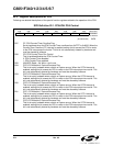
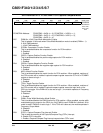
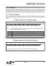
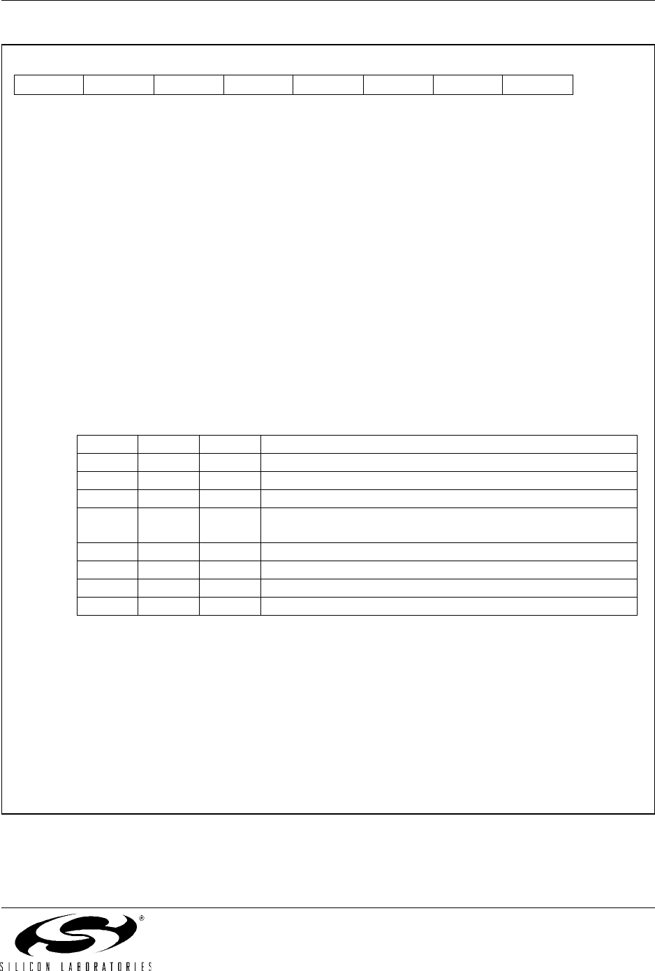
SFR Definition 22.2. PCA0MD: PCA Mode
Bit7: CIDL: PCA Counter/Timer Idle Control.
Specifies PCA behavior when CPU is in Idle Mode.
0: PCA continues to function normally while the system controller is in Idle Mode.
1: PCA operation is suspended while the system controller is in Idle Mode.
Bit6: WDTE: Watchdog Timer Enable
If this bit is set, PCA Module 4 is used as the watchdog timer.
0: Watchdog Timer disabled.
1: PCA Module 4 enabled as Watchdog Timer.
Bit5: WDLCK: Watchdog Timer Lock
This bit enables and locks the Watchdog Timer. When WDLCK is set to ‘1’, the Watchdog
Timer may not be disabled until the next system reset.
0: Watchdog Timer unlocked.
1: Watchdog Timer enabled and locked.
Bit4: UNUSED. Read = 0b, Write = don't care.
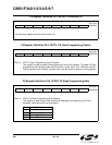
Bits3–1: CPS2–CPS0: PCA Counter/Timer Pulse Select.
These bits select the timebase source for the PCA counter
.
Bit0: ECF: PCA Counter/Timer Overflow Interrupt Enable.
This bit sets the masking of the PCA Counter/Timer Overflow (CF) interrupt.
0: Disable the CF interrupt.
1: Enable a PCA Counter/Timer Overflow interrupt request when CF (PCA0CN.7) is set.
Note: When the WDTE bit is set to ‘1’, the PCA0MD register cannot be modified. To change the
contents of the PCA0MD register, the Watchdog Timer must first be disabled.
R/W R/W R/W R/W R/W R/W R/W R/W Reset Value
CIDL WDTE WDLCK - CPS2 CPS1 CPS0 ECF 01000000
Bit7 Bit6 Bit5 Bit4 Bit3 Bit2 Bit1 Bit0 SFR Address:
0xD9
CPS2 CPS1 CPS0 Timebase
0 0 0 System clock divided by 12
0 0 1 System clock divided by 4
0 1 0 Timer 0 overflow
011
High-to-low transitions on ECI (max rate = system clock
divided by 4)
1 0 0 System clock
1 0 1 External clock divided by 8*
1 1 0 Reserved
1 1 1 Reserved
*Note: External oscillator source divided by 8 is synchronized with the system clock.