


Rev. 0.5 255
C8051F340/1/2/3/4/5/6/7
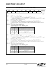
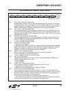
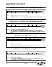
SFR Definition 21.8. TMR2CN: Timer 2 Control
Bit7: TF2H: Timer 2 High Byte Overflow Flag.
Set by hardware when the Timer 2 high byte overflows from 0xFF to 0x00. In 16 bit mode,
this will occur when Timer 2 overflows from 0xFFFF to 0x0000. When the Timer 2 interrupt is
enabled, setting this bit causes the CPU to vector to the Timer 2 interrupt service routine.
TF2H is not automatically cleared by hardware and must be cleared by software.
Bit6: TF2L: Timer 2 Low Byte Overflow Flag.
Set by hardware when the Timer 2 low byte overflows from 0xFF to 0x00. When this bit is
set, an interrupt will be generated if TF2LEN is set and Timer 2 interrupts are enabled. TF2L
will set when the low byte overflows regardless of the Timer 2 mode. This bit is not automat-
ically cleared by hardware.
Bit5: TF2LEN: Timer 2 Low Byte Interrupt Enable.
This bit enables/disables Timer 2 Low Byte interrupts. If TF2LEN is set and Timer 2 inter-
rupts are enabled, an interrupt will be generated when the low byte of Timer 2 overflows.
0: Timer 2 Low Byte interrupts disabled.
1: Timer 2 Low Byte interrupts enabled.
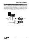
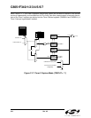
Bit4: T2CE: Timer 2 Capture Enable
0: Capture function disabled.
1: Capture function enabled. The timer is in capture mode, with the capture event selected
by bit T2CSS. Each time a capture event is received, the contents of the Timer 2 registers
(TMR2H and TMR2L) are latched into the Timer 2 reload registers (TMR2RLH and
TMR2RLH), and a Timer 2 interrupt is generated (if enabled).
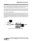
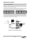
Bit3: T2SPLIT: Timer 2 Split Mode Enable.
When this bit is set, Timer 2 operates as two 8-bit timers with auto-reload.
0: Timer 2 operates in 16-bit auto-reload mode.
1: Timer 2 operates as two 8-bit auto-reload timers.
Bit2: TR2: Timer 2 Run Control.
This bit enables/disables Timer 2. In 8-bit mode, this bit enables/disables TMR2H only;
TMR2L is always enabled in this mode.
0: Timer 2 disabled.
1: Timer 2 enabled.
Bit1: T2CSS: Timer 2 Capture Source Select.
This bit selects the source of a capture event when bit T2CE is set to ‘1’.
0: Capture source is USB SOF event.
1: Capture source is falling edge of Low-Frequency Oscillator.
Bit0: T2XCLK: Timer 2 External Clock Select.
This bit selects the external clock source for Timer 2. If Timer 2 is in 8-bit mode, this bit
selects the external oscillator clock source for both timer bytes. However, the Timer 2 Clock
Select bits (T2MH and T2ML in register CKCON) may still be used to select between the
external clock and the system clock for either timer.
0: Timer 2 external clock selection is the system clock divided by 12.
1: Timer 2 external clock selection is the external clock divided by 8. Note that the external
oscillator source divided by 8 is synchronized with the system clock.
R/W R/W R/W R/W R/W R/W R/W R/W Reset Value
TF2H TF2L TF2LEN T2CE T2SPLIT TR2 T2CSS T2XCLK 00000000
Bit7 Bit6 Bit5 Bit4 Bit3 Bit2 Bit1 Bit0 SFR Address:
(bit addressable)
0xC8