


C8051F340/1/2/3/4/5/6/7
224 Rev. 0.5
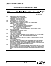
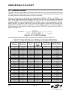
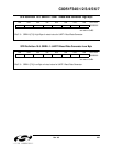
SFR Definition 19.1. SCON1: UART1 Control
Bit7: OVR1: Receive FIFO Overrun Flag.
This bit is used to indicate a receive FIFO overrun condition.
0: Receive FIFO Overrun has not occurred.
1: Receive FIFO Overrun has occurred (an incoming character was discarded due to a full
FIFO).
This bit must be cleared to ‘0’ by software.
Bit6: PERR1: Parity Error Flag.
When parity is enabled, this bit is used to indicate that a parity error has occurred. It is set to
‘1’ when the parity of the oldest byte in the FIFO does not match the selected Parity Type.
0: Parity Error has not occurred.
1: Parity Error has occurred.
This bit must be cleared to ‘0’ by software.
Bit5: THRE1: Transmit Holding Register Empty Flag.
0: Transmit Holding Register not Empty - do not write to SBUF1.
1: Transmit Holding Register Empty - it is safe to write to SBUF1.
Bit4: REN1: Receive Enable.
This bit enables/disables the UART receiver. When disabled, bytes can still be read from the
receive FIFO.
0: UART1 reception disabled.
1: UART1 reception enabled.
Bit3: TBX1: Extra Transmission Bit.
The logic level of this bit will be assigned to the extra transmission bit when XBE1 is set to
‘1’. This bit is not used when Parity is enabled.
Bit2: RBX1: Extra Receive Bit.
RBX1 is assigned the value of the extra bit when XBE1 is set to ‘1’. If XBE1 is cleared to ‘0’,
RBX1 will be assigned the logic level of the first stop bit. This bit is not valid when Parity is
enabled.
Bit1: TI1: Transmit Interrupt Flag.
Set to a ‘1’ by hardware after data has been transmitted, at the beginning of the STOP bit.
When the UART1 interrupt is enabled, setting this bit causes the CPU to vector to the
UART1 interrupt service routine. This bit must be cleared manually by software.
Bit0: RI1: Receive Interrupt Flag.
Set to ‘1’ by hardware when a byte of data has been received by UART1 (set at the STOP bit
sampling time). When the UART1 interrupt is enabled, setting this bit to ‘1’ causes the CPU
to vector to the UART1 interrupt service routine. This bit must be cleared manually by soft-
ware.
R/W R/W R R/W R/W R/W R/W R/W Reset Value
OVR1 PERR1 THRE1 REN1 TBX1 RBX1 TI1 RI1 00100000
Bit7 Bit6 Bit5 Bit4 Bit3 Bit2 Bit1 Bit0
Bit
Addressable
SFR Address:
0xD2