


C8051F340/1/2/3/4/5/6/7
204 Rev. 0.5
17.4.3. Data Register
The SMBus Data register SMB0DAT holds a byte of serial data to be transmitted or one that has just been
received. Software may safely read or write to the data register when the SI flag is set. Software should not
attempt to access the SMB0DAT register when the SMBus is enabled and the SI flag is cleared to logic
0,
as the interface may be in the process of shifting a byte of data into or out of the register.
Data in SMB0DAT is always shifted out MSB first. After a byte has been received, the first bit of received
data is located at the MSB of SMB0DAT. While data is being shifted out, data on the bus is simultaneously
being shifted in. SMB0DAT always contains the last data byte present on the bus. In the event of lost arbi
-
tration, the transition from master transmitter to slave receiver is made with the correct data or address in
SMB0DAT.
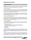
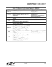
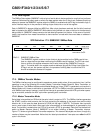
SFR Definition 17.3. SMB0DAT: SMBus Data
17.5. SMBus Transfer Modes
The SMBus interface may be configured to operate as master and/or slave. At any particular time, it will be
operating in one of the following four modes: Master Transmitter, Master Receiver, Slave Transmitter, or
Slave Receiver. The SMBus interface enters Master Mode any time a START is generated, and remains in
Master Mode until it loses an arbitration or generates a STOP. An SMBus interrupt is generated at the end
of all SMBus byte frames; however, note that the interrupt is generated before the ACK cycle when operat
-
ing as a receiver, and after the ACK cycle when operating as a transmitter.
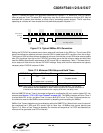
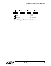
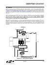
17.5.1. Master Transmitter Mode
Serial data is transmitted on SDA while the serial clock is output on SCL. The SMBus interface generates
the START condition and transmits the first byte containing the address of the target slave and the data
direction bit. In this case the data direction bit (R/W) will be logic
0 (WRITE). The master then transmits
one or more bytes of serial data. After each byte is transmitted, an acknowledge bit is generated by the
slave. The transfer is ended when the STO bit is set and a STOP is generated. Note that the interface will
switch to Master Receiver Mode if SMB0DAT is not written following a Master Transmitter interrupt.
Figure 17.5 shows a typical Master Transmitter sequence. Two transmit data bytes are shown, though any
number of bytes may be transmitted. Notice that the ‘data byte transferred’ interrupts occur after the ACK
cycle in this mode.
Bits7-0: SMB0DAT: SMBus Data.
The SMB0DAT register contains a byte of data to be transmitted on the SMBus serial inter-
face or a byte that has just been received on the SMBus serial interface. The CPU can read
from or write to this register whenever the SI serial interrupt flag (SMB0CN.0) is set to
logic 1. The serial data in the register remains stable as long as the SI flag is set. When the
SI flag is not set, the system may be in the process of shifting data in/out and the CPU
should not attempt to access this register.
R/W R/W R/W R/W R/W R/W R/W R/W Reset Value
00000000
Bit7 Bit6 Bit5 Bit4 Bit3 Bit2 Bit1 Bit0
SFR Address:
0xC2