


Rev. 0.5 137
C8051F340/1/2/3/4/5/6/7
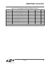
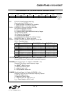
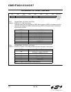
SFR Definition 14.2. OSCICL: Internal H-F Oscillator Calibration
14.2. Programmable Internal Low-Frequency (L-F) Oscillator
The C8051F340/1/2/3/4/5 devices include a programmable internal oscillator which operates at a nominal
frequency of 80
kHz. The low-frequency oscillator circuit includes a divider that can be changed to divide
the clock by 1, 2, 4, or 8, using the OSCLD bits in the OSCLCN register (see
SFR Definition 14.3). Addi-
tionally, the OSCLF bits (OSCLCN5:2) can be used to adjust the oscillator’s output frequency.
14.2.1. Calibrating the Internal L-F Oscillator
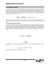
Timers 2 and 3 include capture functions that can be used to capture the oscillator frequency, when run-
ning from a known time base. When either Timer 2 or Timer 3 is configured for L-F Oscillator Capture
Mode, a falling edge (Timer 2) or rising edge (Timer 3) of the low-frequency oscillator’s output will cause a
capture event on the corresponding timer. As a capture event occurs, the current timer value
(TMRnH:TMRnL) is copied into the timer reload registers (TMRnRLH:TMRnRLL). By recording the differ
-
ence between two successive timer capture values, the low-frequency oscillator’s period can be calcu-
lated. The OSCLF bits can then be adjusted to produce the desired oscillator period.
Bits4–0: OSCCAL: Oscillator Calibration Value
These bits determine the internal H-F oscillator period. When set to 00000b, the oscillator
operates at its fastest setting. When set to 11111b, the oscillator operates at is slowest set-
ting. The contents of this register are factory calibrated to produce a 12 MHz internal oscilla-
tor frequency.
Note: The contents of this register are undefined when Clock Recovery is enabled. See Section
“16.4. USB Clock Configuration” on page 170 for details on Clock Recovery.
R/W R/W R/W R/W R/W R/W R/W R/W Reset Value
--- OSCCAL Variable
Bit7 Bit6 Bit5 Bit4 Bit3 Bit2 Bit1 Bit0 SFR Address:
0xB3