


Rev. 0.5 247
C8051F340/1/2/3/4/5/6/7
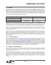
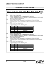
SFR Definition 21.1. TCON: Timer Control
Bit7: TF1: Timer 1 Overflow Flag.
Set by hardware when Timer 1 overflows. This flag can be cleared by software but is auto-
matically cleared when the CPU vectors to the Timer 1 interrupt service routine.
0: No Timer 1 overflow detected.
1: Timer 1 has overflowed.
Bit6: TR1: Timer 1 Run Control.
0: Timer 1 disabled.
1: Timer 1 enabled.
Bit5: TF0: Timer 0 Overflow Flag.
Set by hardware when Timer 0 overflows. This flag can be cleared by software but is auto-
matically cleared when the CPU vectors to the Timer 0 interrupt service routine.
0: No Timer 0 overflow detected.
1: Timer 0 has overflowed.
Bit4: TR0: Timer 0 Run Control.
0: Timer 0 disabled.
1: Timer 0 enabled.
Bit3: IE1: External Interrupt 1.
This flag is set by hardware when an edge/level of type defined by IT1 is detected. It can be
cleared by software but is automatically cleared when the CPU vectors to the External Inter-
rupt 1 service routine if IT1 = 1. When IT1 = 0, this flag is set to ‘1’ when /INT1 is active as
defined by bit IN1PL in register INT01CF (see SFR Definition 9.13).
Bit2: IT1: Interrupt 1 Type Select.
This bit selects whether the configured /INT1 interrupt will be edge or level sensitive. /INT1
is configured active low or high by the IN1PL bit in the IT01CF register (see SFR Definition
9.13).
0: /INT1 is level triggered.
1: /INT1 is edge triggered.
Bit1: IE0: External Interrupt 0.
This flag is set by hardware when an edge/level of type defined by IT0 is detected. It can be
cleared by software but is automatically cleared when the CPU vectors to the External Inter-
rupt 0 service routine if IT0 = 1. When IT0 = 0, this flag is set to ‘1’ when /INT0 is active as
defined by bit IN0PL in register INT01CF (see SFR Definition 9.13).
Bit0: IT0: Interrupt 0 Type Select.
This bit selects whether the configured /INT0 interrupt will be edge or level sensitive. /INT0
is configured active low or high by the IN0PL bit in register IT01CF (see SFR Definition
9.13).
0: /INT0 is level triggered.
1: /INT0 is edge triggered.
R/W R/W R/W R/W R/W R/W R/W R/W Reset Value
TF1 TR1 TF0 TR0 IE1 IT1 IE0 IT0 00000000
Bit7 Bit6 Bit5 Bit4 Bit3 Bit2 Bit1 Bit0 SFR Address:
(bit addressable)
0x88