


C8051F340/1/2/3/4/5/6/7
246 Rev. 0.5
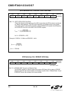
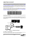
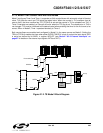
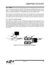
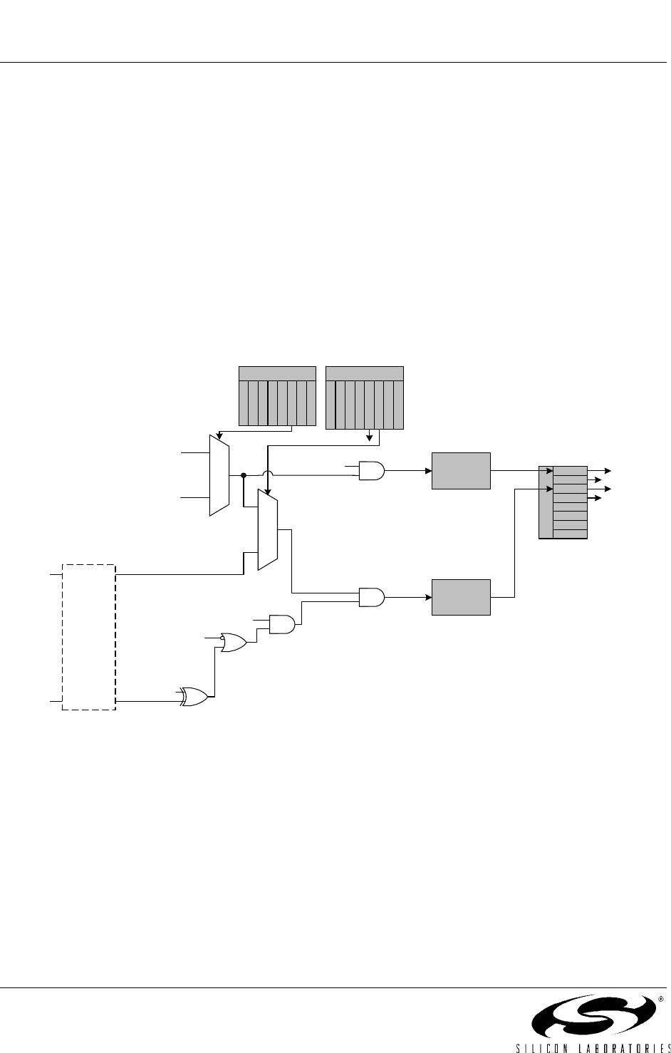
21.1.4. Mode 3: Two 8-bit Counter/Timers (Timer 0 Only)
In Mode 3, Timer 0 is configured as two separate 8-bit counter/timers held in TL0 and TH0. The counter/
timer in TL0 is controlled using the Timer 0 control/status bits in TCON and TMOD: TR0, C/T0, GATE0 and
TF0. TL0 can use either the system clock or an external input signal as its timebase. The TH0 register is
restricted to a timer function sourced by the system clock or prescaled clock. TH0 is enabled using the
Timer 1 run control bit TR1. TH0 sets the Timer 1 overflow flag TF1 on overflow and thus controls the
Timer 1 interrupt.
Timer 1 is inactive in Mode 3. When Timer 0 is operating in Mode 3, Timer 1 can be operated in Modes 0,
1 or 2, but cannot be clocked by external signals nor set the TF1 flag and generate an interrupt. However,
the Timer 1 overflow can be used to generate baud rates for the SMBus and/or UART, and/or initiate ADC
conversions. While Timer 0 is operating in Mode 3, Timer 1 run control is handled through its mode set
-
tings. To run Timer 1 while Timer 0 is in Mode 3, set the Timer 1 Mode as 0, 1, or 2. To disable Timer 1,
configure it for Mode 3.
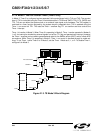
Figure 21.3. T0 Mode 3 Block Diagram
TL0
(8 bits)
TMOD
0
1
TCON
TF0
TR0
TR1
TF1
IE1
IT1
IE0
IT0
Interrupt
Interrupt
0
1
SYSCLK
Pre-scaled Clock
TR1
TH0
(8 bits)
T
1
M
1
T
1
M
0
C
/
T
1
G
A
T
E
1
G
A
T
E
0
C
/
T
0
T
0
M
1
T
0
M
0
TR0
GATE0
IN0PL
XOR
/INT0
T0
Crossbar
CKCON
T
3
M
H
T
3
M
L
S
C
A
0
S
C
A
1
T
0
M
T
2
M
H
T
2
M
L
T
1
M