


Rev. 0.5 213
C8051F340/1/2/3/4/5/6/7
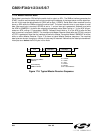
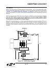
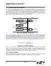
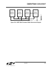
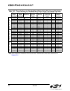
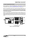
Figure 18.3. UART Interconnect Diagram
18.2.1. 8-Bit UART
8-Bit UART mode uses a total of 10 bits per data byte: one start bit, eight data bits (LSB first), and one stop
bit. Data are transmitted LSB first from the TX0 pin and received at the RX0 pin. On receive, the eight data
bits are stored in SBUF0 and the stop bit goes into RB80 (SCON0.2).
Data transmission begins when software writes a data byte to the SBUF0 register. The TI0 Transmit Inter-
rupt Flag (SCON0.1) is set at the end of the transmission (the beginning of the stop-bit time). Data recep-
tion can begin any time after the REN0 Receive Enable bit (SCON0.4) is set to logic 1. After the stop bit is
received, the data byte will be loaded into the SBUF0 receive register if the following conditions are met:
RI0 must be logic
0, and if MCE0 is logic 1, the stop bit must be logic 1. In the event of a receive data over-
run, the first received 8 bits are latched into the SBUF0 receive register and the following overrun data bits
are lost.
If these conditions are met, the eight bits of data is stored in SBUF0, the stop bit is stored in RB80 and the
RI0 flag is set. If these conditions are not met, SBUF0 and RB80 will not be loaded and the RI0 flag will not
be set. An interrupt will occur if enabled when either TI0 or RI0 is set.
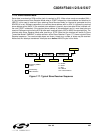
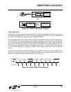
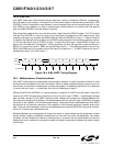
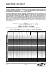
Figure 18.4. 8-Bit UART Timing Diagram
OR
RS-232
C8051Fxxx
RS-232
LEVEL
XLTR
TX
RX
C8051Fxxx
RX
TX
MCU
RX
TX
D1D0 D2 D3 D4 D5 D6 D7
START
BIT
MARK
STOP
BIT
BIT TIMES
BIT SAMPLING
SPACE