


C8051F340/1/2/3/4/5/6/7
176 Rev. 0.5
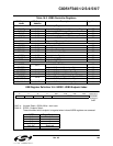
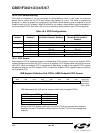
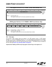
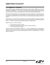
USB Register Definition 16.9. FRAMEL: USB0 Frame Number Low
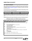
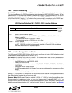
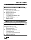
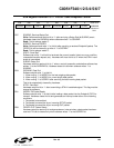
USB Register Definition 16.10. FRAMEH: USB0 Frame Number High
16.8. Interrupts
The read-only USB0 interrupt flags are located in the USB registers shown in USB Register
Definition 16.11 through USB Register Definition 16.13. The associated interrupt enable bits are located in
the USB registers shown in USB Register Definition 16.14 through USB Register Definition 16.16. A USB0
interrupt is generated when any of the USB interrupt flags is set to ‘1’. The USB0 interrupt is enabled via
the EIE1 SFR (see
Section “9.3. Interrupt Handler” on page 87).
Important Note: Reading a USB interrupt flag register resets all flags in that register to ‘0’.
Bits7-0: Frame Number Low
This register contains bits7-0 of the last received frame number.
RRRRRRRRReset Value
Frame Number Low 00000000
Bit7 Bit6 Bit5 Bit4 Bit3 Bit2 Bit1 Bit0 USB Address:
0x0C
Bits7-3: Unused. Read = 0. Write = don’t care.
Bits2-0: Frame Number High Byte
This register contains bits10-8 of the last received frame number.
RRRRRRRRReset Value
- - - - - Frame Number High 00000000
Bit7 Bit6 Bit5 Bit4 Bit3 Bit2 Bit1 Bit0 USB Address:
0x0D