


Rev. 0.5 119
C8051F340/1/2/3/4/5/6/7
13.3. Configuring the External Memory Interface
Configuring the External Memory Interface consists of five steps:
1. Configure the Output Modes of the associated port pins as either push-pull or open-drain
(push-pull is most common), and skip the associated pins in the crossbar.
2. Configure Port latches to “park” the EMIF pins in a dormant state (usually by setting them to
logic ‘1’).
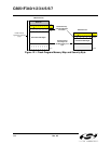
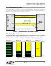
3. Select Multiplexed mode or Non-multiplexed mode.
4. Select the memory mode (on-chip only, split mode without bank select, split mode with bank
select, or off-chip only).
5. Set up timing to interface with off-chip memory or peripherals.
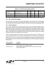
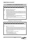
Each of these five steps is explained in detail in the following sections. The Port selection, Multiplexed
mode selection, and Mode bits are located in the EMI0CF register shown in
SFR Definition 13.2.
13.4. Port Configuration
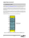
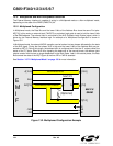
The External Memory Interface appears on Ports 4, 3, 2, and 1 when it is used for off-chip memory access.
When the EMIF is used, the Crossbar should be configured to skip over the control lines P1.7 (/WR), P1.6
(/RD), and if multiplexed mode is selected P1.3 (ALE) using the P1SKIP register. For more information
about configuring the Crossbar, see
Section “Figure 15.1. Port I/O Functional Block Diagram (Port 0
through Port 3)” on page 147.
The External Memory Interface claims the associated Port pins for memory operations ONLY during the
execution of an off-chip MOVX instruction. Once the MOVX instruction has completed, control of the Port
pins reverts to the Port latches or to the Crossbar settings for those pins. See
Section “15. Port Input/
Output” on page 147 for more information about the Crossbar and Port operation and configuration. The
Port latches should be explicitly configured to ‘park’ the External Memory Interface pins in a dor-
mant state, most commonly by setting them to a logic 1.
During the execution of the MOVX instruction, the External Memory Interface will explicitly disable the driv-
ers on all Port pins that are acting as Inputs (Data[7:0] during a READ operation, for example). The Output
mode of the Port pins (whether the pin is configured as Open-Drain or Push-Pull) is unaffected by the
External Memory Interface operation, and remains controlled by the PnMDOUT registers. In most cases,
the output modes of all EMIF pins should be configured for push-pull mode.