


C8051F340/1/2/3/4/5/6/7
266 Rev. 0.5
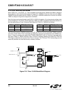
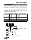
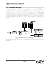
22.2.1. Edge-triggered Capture Mode
In this mode, a valid transition on the CEXn pin causes the PCA to capture the value of the PCA counter/
timer and load it into the corresponding module's 16-bit capture/compare register (PCA0CPLn and
PCA0CPHn). The CAPPn and CAPNn bits in the PCA0CPMn register are used to select the type of transi
-
tion that triggers the capture: low-to-high transition (positive edge), high-to-low transition (negative edge),
or either transition (positive or negative edge). When a capture occurs, the Capture/Compare Flag (CCFn)
in PCA0CN is set to logic 1 and an interrupt request is generated if CCF interrupts are enabled. The CCFn
bit is not automatically cleared by hardware when the CPU vectors to the interrupt service routine, and
must be cleared by software. If both CAPPn and CAPNn bits are set to logic 1, then the state of the Port
pin associated with CEXn can be read directly to determine whether a rising-edge or falling-edge caused
the capture.
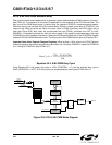
Figure 22.4. PCA Capture Mode Diagram
Note: The CEXn input signal must remain high or low for at least 2 system clock cycles to be recognized by
the hardware.
PCA0L
PCA0CPLn
PCA
Timebase
CEXn
CrossbarPort I/O
PCA0H
Capture
PCA0CPHn
0
1
0
1
(to CCFn)
PCA0CPMn
P
W
M
1
6
n
E
C
O
M
n
E
C
C
F
n
T
O
G
n
P
W
M
n
C
A
P
P
n
C
A
P
N
n
M
A
T
n
PCA0CN
C
F
C
R
C
C
F
0
C
C
F
2
C
C
F
1
C
C
F
4
C
C
F
3
PCA Interrupt
0 000xx