


Rev. 0.5 171
C8051F340/1/2/3/4/5/6/7
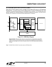
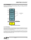
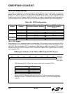
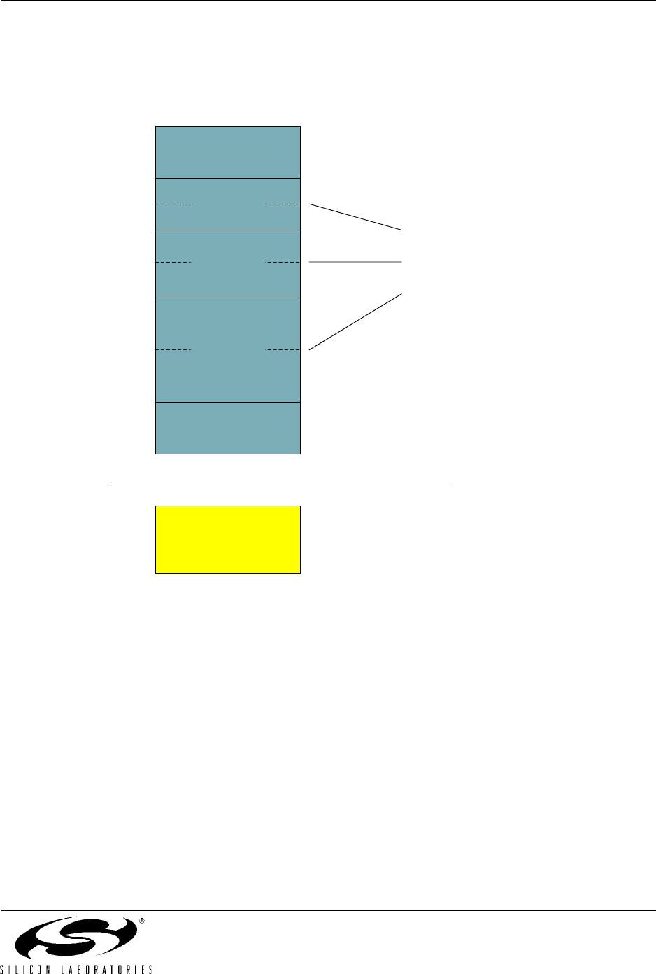
16.5. FIFO Management
1024 bytes of on-chip XRAM are used as FIFO space for USB0. This FIFO space is split between
Endpoints0-3 as shown in
Figure 16.3. FIFO space allocated for Endpoints1-3 is configurable as IN, OUT,
or both (Split Mode: half IN, half OUT).
Figure 16.3. USB FIFO Allocation
16.5.1. FIFO Split Mode
The FIFO space for Endpoints1-3 can be split such that the upper half of the FIFO space is used by the IN
endpoint, and the lower half is used by the OUT endpoint. For example: if the Endpoint3 FIFO is configured
for Split Mode, the upper 256 bytes (0x0540 to 0x063F) are used by Endpoint3 IN and the lower 256 bytes
(0x0440 to 0x053F) are used by Endpoint3 OUT.
If an endpoint FIFO is not configured for Split Mode, that endpoint IN/OUT pair’s FIFOs are combined to
form a single IN
or OUT FIFO. In this case only one direction of the endpoint IN/OUT pair may be used at
a time. The endpoint direction (IN/OUT) is determined by the DIRSEL bit in the corresponding endpoint’s
EINCSRH register (see
SFR Definition 16.20).
Endpoint0
(64 bytes)
Configurable as
IN, OUT, or both (Split
Mode)
Free
(64 bytes)
0x0400
0x043F
0x0440
0x063F
0x0640
0x073F
0x0740
0x07BF
0x07C0
0x07FF
User XRAM
(1024 bytes)
0x0000
0x03FF
USB Clock Domain
System Clock Domain
Endpoint1
(128 bytes)
Endpoint2
(256 bytes)
Endpoint3
(512 bytes)