


Rev. 0.5 271
C8051F340/1/2/3/4/5/6/7
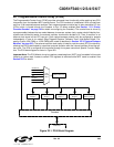
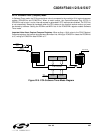
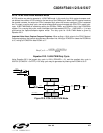
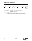
22.2.6. 16-Bit Pulse Width Modulator Mode
A PCA module may also be operated in 16-Bit PWM mode. In this mode, the 16-bit capture/compare mod-
ule defines the number of PCA clocks for the low time of the PWM signal. When the PCA counter matches
the module contents, the output on CEXn is asserted high; when the counter overflows, CEXn is asserted
low. To output a varying duty cycle, new value writes should be synchronized with PCA CCFn match inter
-
rupts. 16-Bit PWM Mode is enabled by setting the ECOMn, PWMn, and PWM16n bits in the PCA0CPMn
register. For a varying duty cycle, match interrupts should be enabled (ECCFn = 1 AND MATn = 1) to help
synchronize the capture/compare register writes. The duty cycle for 16-Bit PWM Mode is given by
Equation 22.3.
Important Note About Capture/Compare Registers: When writing a 16-bit value to the PCA0 Capture/
Compare registers, the low byte should always be written first. Writing to PCA0CPLn clears the ECOMn bit
to ‘0’; writing to PCA0CPHn sets ECOMn to ‘1’.
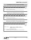
Equation 22.3. 16-Bit PWM Duty Cycle
Using Equation 22.3, the largest duty cycle is 100% (PCA0CPn = 0), and the smallest duty cycle is
0.0015% (PCA0CPn = 0xFFFF). A 0% duty cycle may be generated by clearing the ECOMn bit to ‘0’.
Figure 22.9. PCA 16-Bit PWM Mode
DutyCycle
65536 PCA0CPn–()
65536
-----------------------------------------------------
=
PCA0CPLnPCA0CPHn
Enable
PCA Timebase
00x0 x
PCA0CPMn
P
W
M
1
6
n
E
C
O
M
n
E
C
C
F
n
T
O
G
n
P
W
M
n
C
A
P
P
n
C
A
P
N
n
M
A
T
n
1
16-bit Comparator
CEXn
Crossbar Port I/O
Overflow
Q
Q
SET
CLR
S
R
match
PCA0H PCA0L
ENB
ENB
0
1
Write to
PCA0CPLn
Write to
PCA0CPHn
Reset