


Rev. 0.5 249
C8051F340/1/2/3/4/5/6/7
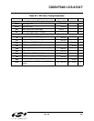
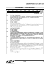
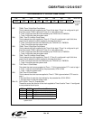
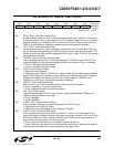
SFR Definition 21.3. CKCON: Clock Control
Bit7: T3MH: Timer 3 High Byte Clock Select.
This bit selects the clock supplied to the Timer 3 high byte if Timer 3 is configured in split
8-bit timer mode. T3MH is ignored if Timer 3 is in any other mode.
0: Timer 3 high byte uses the clock defined by the T3XCLK bit in TMR3CN.
1: Timer 3 high byte uses the system clock.
Bit6: T3ML: Timer 3 Low Byte Clock Select.
This bit selects the clock supplied to Timer 3. If Timer 3 is configured in split 8-bit timer
mode, this bit selects the clock supplied to the lower 8-bit timer.
0: Timer 3 low byte uses the clock defined by the T3XCLK bit in TMR3CN.
1: Timer 3 low byte uses the system clock.
Bit5: T2MH: Timer 2 High Byte Clock Select.
This bit selects the clock supplied to the Timer 2 high byte if Timer 2 is configured in split
8-bit timer mode. T2MH is ignored if Timer 2 is in any other mode.
0: Timer 2 high byte uses the clock defined by the T2XCLK bit in TMR2CN.
1: Timer 2 high byte uses the system clock.
Bit4: T2ML: Timer 2 Low Byte Clock Select.
This bit selects the clock supplied to Timer 2. If Timer 2 is configured in split 8-bit timer
mode, this bit selects the clock supplied to the lower 8-bit timer.
0: Timer 2 low byte uses the clock defined by the T2XCLK bit in TMR2CN.
1: Timer 2 low byte uses the system clock.
Bit3: T1M: Timer 1 Clock Select.
This select the clock source supplied to Timer 1. T1M is ignored when C/T1 is set to logic 1.
0: Timer 1 uses the clock defined by the prescale bits, SCA1-SCA0.
1: Timer 1 uses the system clock.
Bit2: T0M: Timer 0 Clock Select.
This bit selects the clock source supplied to Timer 0. T0M is ignored when C/T0 is set to
logic 1.
0: Counter/Timer 0 uses the clock defined by the prescale bits, SCA1-SCA0.
1: Counter/Timer 0 uses the system clock.
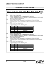
Bits1–0: SCA1-SCA0: Timer 0/1 Prescale Bits.
These bits control the division of the clock supplied to Timer 0 and/or Timer 1 if configured
to use prescaled clock inputs.
R/W R/W R/W R/W R/W R/W R/W R/W Reset Value
T3MH T3ML T2MH T2ML T1M T0M SCA1 SCA0 00000000
Bit7 Bit6 Bit5 Bit4 Bit3 Bit2 Bit1 Bit0 SFR Address:
0x8E
SCA1 SCA0 Prescaled Clock
0 0 System clock divided by 12
0 1 System clock divided by 4
1 0 System clock divided by 48
1 1 External clock divided by 8
Note: External clock divided by 8 is synchronized with the
system clock.