


Rev. 0.5 199
C8051F340/1/2/3/4/5/6/7
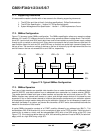
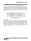
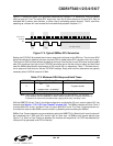
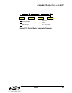
Figure 17.4 shows the typical SCL generation described by Equation 17.2. Notice that T
HIGH
is typically
twice as large as T
LOW
. The actual SCL output may vary due to other devices on the bus (SCL may be
extended low by slower slave devices, or driven low by contending master devices). The bit rate when
operating as a master will never exceed the limits defined by equation
Equation 17.1.
Figure 17.4. Typical SMBus SCL Generation
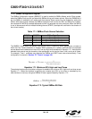
Setting the EXTHOLD bit extends the minimum setup and hold times for the SDA line. The minimum SDA
setup time defines the absolute minimum time that SDA is stable before SCL transitions from low-to-high.
The minimum SDA hold time defines the absolute minimum time that the current SDA value remains stable
after SCL transitions from high-to-low. EXTHOLD should be set so that the minimum setup and hold times
meet the SMBus Specification requirements of 250
ns and 300 ns, respectively. Table 17.2 shows the min-
imum setup and hold times for the two EXTHOLD settings. Setup and hold time extensions are typically
necessary when SYSCLK is above 10
MHz.
With the SMBTOE bit set, Timer 3 should be configured to overflow after 25 ms in order to detect SCL low
timeouts (see
Section “17.3.3. SCL Low Timeout” on page 196). The SMBus interface will force Timer 3
to reload while SCL is high, and allow Timer 3 to count when SCL is low. The Timer 3 interrupt service rou-
tine should be used to reset SMBus communication by disabling and re-enabling the SMBus.
SMBus Free Timeout detection can be enabled by setting the SMBFTE bit. When this bit is set, the bus will
be considered free if SDA and SCL remain high for more than 10
SMBus clock source periods (see
Figure 17.4). When a Free Timeout is detected, the interface will respond as if a STOP was detected (an
interrupt will be generated, and STO will be set).
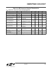
Table 17.2. Minimum SDA Setup and Hold Times
EXTHOLD Minimum SDA Setup Time Minimum SDA Hold Time
0
T
low
- 4 system clocks
OR
1 system clock + s/w delay*
3 system clocks
1 11 system clocks 12 system clocks
*Note: Setup Time for ACK bit transmissions and the MSB of all data transfers. The s/w delay
occurs between the time SMB0DAT or ACK is written and when SI is cleared. Note that if SI
is cleared in the same write that defines the outgoing ACK value, s/w delay is zero.
SCL
Timer Source
Overflows
SCL High TimeoutT
Low
T
High