


C8051F340/1/2/3/4/5/6/7
174 Rev. 0.5
“14. Oscillators” on page 135 for more details on internal oscillator configuration, including the Suspend
mode feature of the internal oscillator.
USB0 exits Suspend mode when any of the following occur: (1) Resume signaling is detected or gener-
ated, (2) Reset signaling is detected, or (3) a device or USB reset occurs. If suspended, the internal oscil-
lator will exit Suspend mode upon any of the above listed events.
Resume Signaling: USB0 will exit Suspend mode if Resume signaling is detected on the bus. A Resume
interrupt will be generated upon detection if enabled (RESINTE = ‘1’). Software may force a Remote
Wakeup by writing ‘1’ to the RESUME bit (POWER.2). When forcing a Remote Wakeup, software should
write RESUME = ‘0’ to end Resume signaling 10-15
ms after the Remote Wakeup is initiated (RESUME =
‘1’).
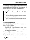
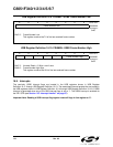
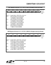
ISO Update: When software writes ‘1’ to the ISOUP bit (POWER.7), the ISO Update function is enabled.
With ISO Update enabled, new packets written to an ISO IN endpoint will not be transmitted until a new
Start-Of-Frame (SOF) is received. If the ISO IN endpoint receives an IN token before a SOF, USB0 will
transmit a zero-length packet. When ISOUP = ‘1’, ISO Update is enabled for all ISO endpoints.
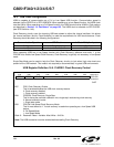
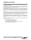
USB Enable: USB0 is disabled following a Power-On-Reset (POR). USB0 is enabled by clearing the
USBINH bit (POWER.4). Once written to ‘0’, the USBINH can only be set to ‘1’ by one of the following: (1)
a Power-On-Reset (POR), or (2) an asynchronous USB0 reset generated by writing ‘1’ to the USBRST bit
(POWER.3).
Software should perform all USB0 configuration before enabling USB0. The configuration sequence
should be performed as follows:
Step 1. Select and enable the USB clock source.
Step 2. Reset USB0 by writing USBRST= ‘1’.
Step 3. Configure and enable the USB Transceiver.
Step 4. Perform any USB0 function configuration (interrupts, Suspend detect).
Step 5. Enable USB0 by writing USBINH = ‘0’.