


C8051F340/1/2/3/4/5/6/7
172 Rev. 0.5
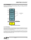
16.5.2. FIFO Double Buffering
FIFO slots for Endpoints1-3 can be configured for double-buffered mode. In this mode, the maximum
packet size is halved and the FIFO may contain two packets at a time. This mode is available for
Endpoints1-3. When an endpoint is configured for Split Mode, double buffering may be enabled for the IN
Endpoint and/or the OUT endpoint. When Split Mode is not enabled, double-buffering may be enabled for
the entire endpoint FIFO. See
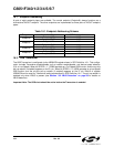
Table 16.3 for a list of maximum packet sizes for each FIFO configuration.
16.5.1. FIFO Access
Each endpoint FIFO is accessed through a corresponding FIFOn register. A read of an endpoint FIFOn
register unloads one byte from the FIFO; a write of an endpoint FIFOn register loads one byte into the end
-
point FIFO. When an endpoint FIFO is configured for Split Mode, a read of the endpoint FIFOn register
unloads one byte from the OUT endpoint FIFO; a write of the endpoint FIFOn register loads one byte into
the IN endpoint FIFO.
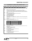
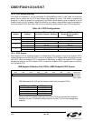
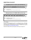
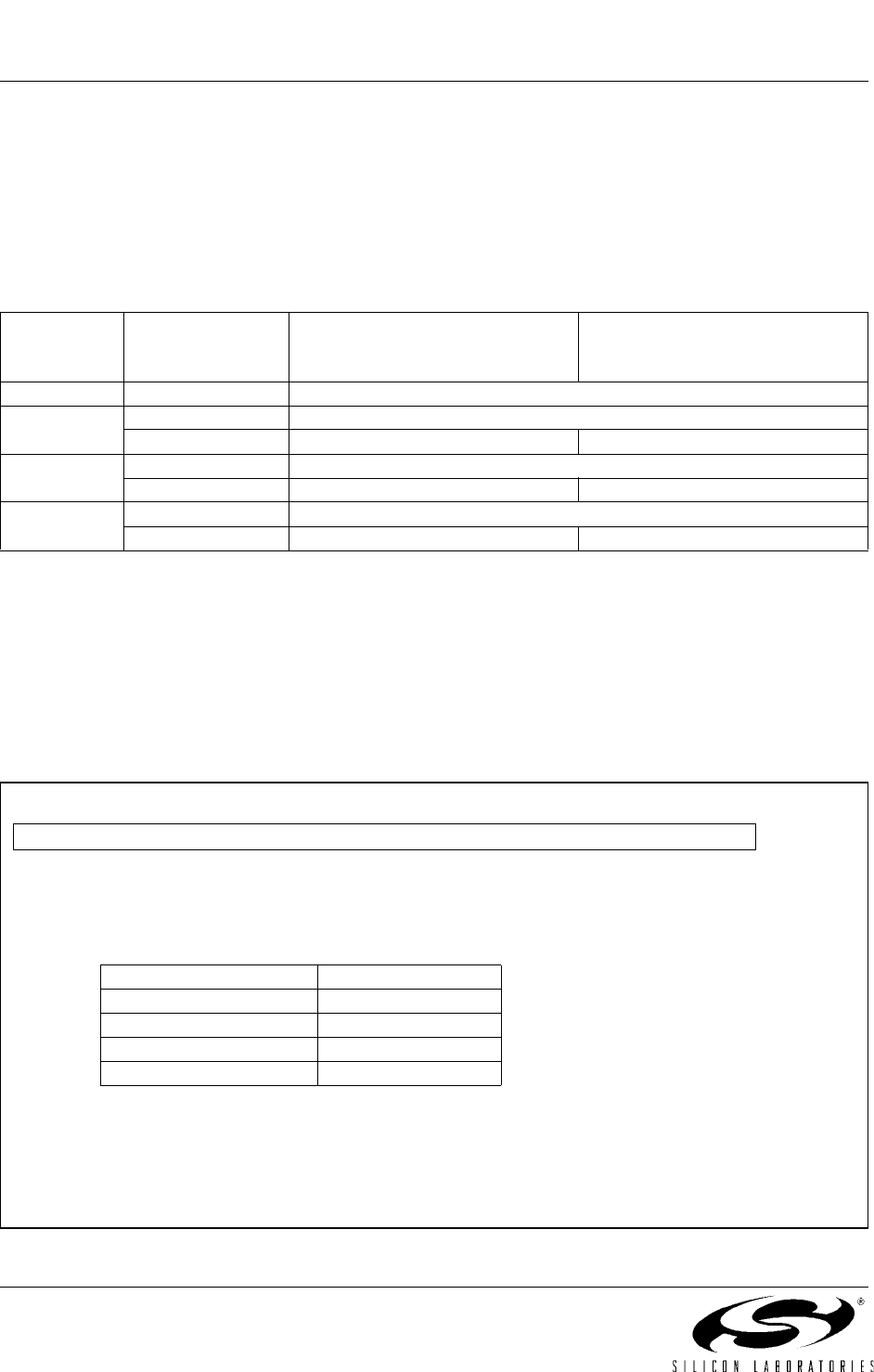
USB Register Definition 16.6. FIFOn: USB0 Endpoint FIFO Access
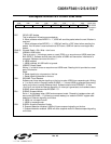
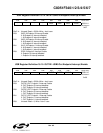
Table 16.3. FIFO Configurations
Endpoint
Number
Split Mode
Enabled?
Maximum IN Packet Size (Dou-
ble Buffer Disabled / Enabled)
Maximum OUT Packet Size
(Double Buffer Disabled /
Enabled)
0N/A 64
1
N 128 / 64
Y 64 / 32 64 / 32
2
N 256 / 128
Y 128 / 64 128 / 64
3
N 512 / 256
Y 256 / 128 256 / 128
USB Addresses 0x20–0x23 provide access to the 4 pairs of endpoint FIFOs:
Writing to the FIFO address loads data into the IN FIFO for the corresponding endpoint.
Reading from the FIFO address unloads data from the OUT FIFO for the corresponding
endpoint.
R/W R/W R/W R/W R/W R/W R/W R/W Reset Value
FIFODATA 00000000
Bit7 Bit6 Bit5 Bit4 Bit3 Bit2 Bit1 Bit0 USB Address:
0x20 - 0x23
IN/OUT Endpoint FIFO USB Address
00x20
10x21
20x22
30x23