


C8051F340/1/2/3/4/5/6/7
122 Rev. 0.5
13.5. Multiplexed and Non-multiplexed Selection
The External Memory Interface is capable of acting in a Multiplexed mode or a Non-multiplexed mode,
depending on the state of the EMD2 (EMI0CF.4) bit.
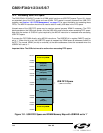
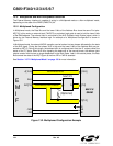
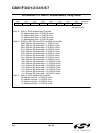
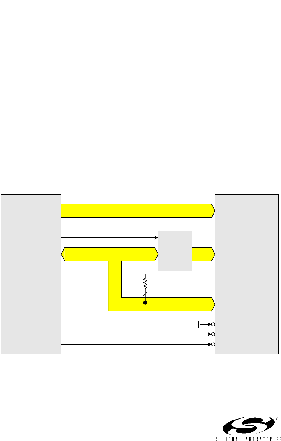
13.5.1. Multiplexed Configuration
In Multiplexed mode, the Data Bus and the lower 8-bits of the Address Bus share the same Port pins:
AD[7:0]. In this mode, an external latch (74HC373 or equivalent logic gate) is used to hold the lower 8-bits
of the RAM address. The external latch is controlled by the ALE (Address Latch Enable) signal, which is
driven by the External Memory Interface logic. An example of a Multiplexed Configuration is shown in
Figure 13.2.
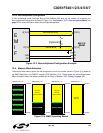
In Multiplexed mode, the external MOVX operation can be broken into two phases delineated by the state
of the ALE signal. During the first phase, ALE is high and the lower 8-bits of the Address Bus are pre
-
sented to AD[7:0]. During this phase, the address latch is configured such that the ‘Q’ outputs reflect the
states of the ‘D’ inputs. When ALE falls, signaling the beginning of the second phase, the address latch
outputs remain fixed and are no longer dependent on the latch inputs. Later in the second phase, the Data
Bus controls the state of the AD[7:0] port at the time /RD or /WR is asserted.
See Section “13.7.2. Multiplexed Mode” on page 130 for more information.
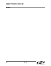
Figure 13.2. Multiplexed Configuration Example
ADDRESS/DATA BUS
ADDRESS BUS
E
M
I
F
A[15:8]
AD[7:0]
/WR
/RD
ALE
64K X 8
SRAM
OE
WE
I/O[7:0]
74HC373
G
DQ
A[15:8]
A[7:0]
CE
V
DD
8
(Optional)