


Shure cartridges can be used in DJ or Hi-Fi applications.
Note: The M70BX is not recommended for heavy scratching.
25, 35, and 44 Series
Phono Cartridges
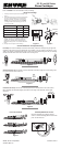
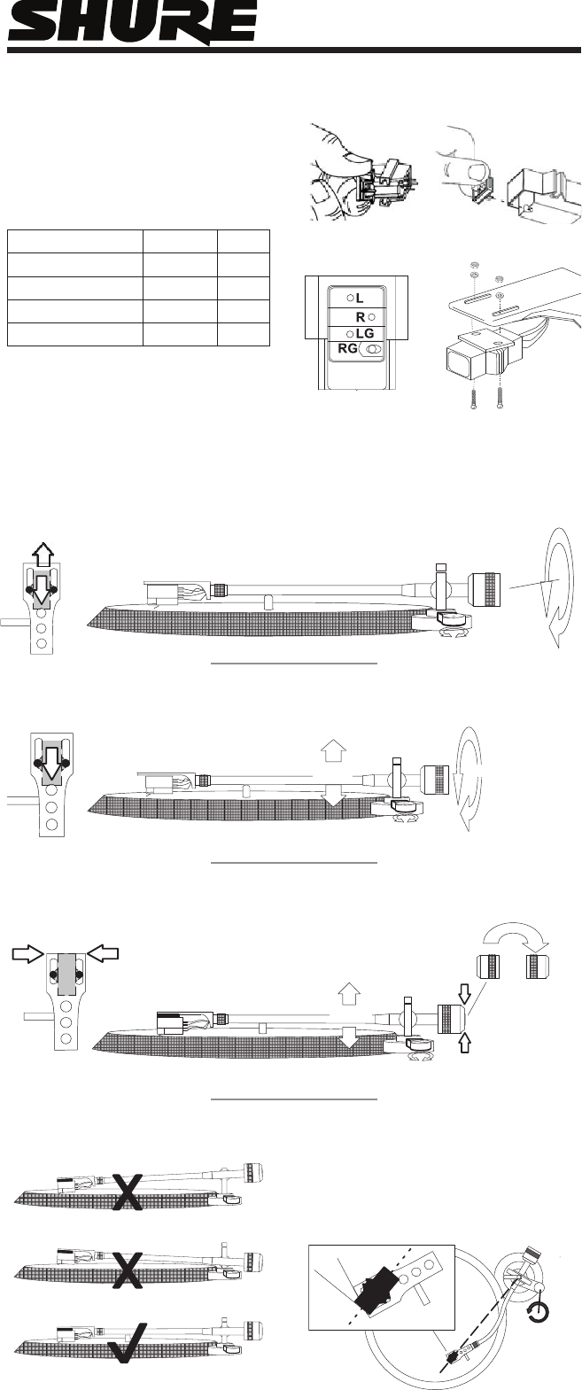
Install Your Cartridge
Carefully remove the stylus from the cartridge. See 1.
Figure 1.
Use needle-nose pliers to connect the colored wires 2.
from the tonearm headshell to the corresponding
pins on the cartridge. See Table 1 and Figure 2.
NOTE: The larger terminal goes onto the M25C
cartridge and the smaller terminal goes onto the
arm of the turntable.
HEADSHELL WIRE COLOR PIN
RIGHT “HOT” RED R
RIGHT GROUND GREEN RG
LEFT “HOT” WHITE L
LEFT GROUND BLUE LG
Figure 2
Figure 3
Figure 4
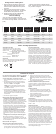
Standard DJ Setup: Mount cartridge at rear of headshell. Set tonearm height to 4-5. Set tracking force
to 3 grams. Set anti-skate control to 0.
Figure 5
Choose a Method for Cartridge Positioning
Hi-Fi Setup: For maximum fidelity and minimal record wear, position the cartridge using an alignment
protractor or the overhang gauge supplied with your turntable. Level your tonearm (See Figure 7). Use
Table 2 and “Setting a Precise Tracking Force”, below, to set the typical tracking force for your cartridge.
Set the anti-skate control to the same number as the tracking force.
4 - 5
3 grams
4 - 5
0
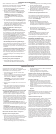
Unorthodox DJ Setup: Reverse the counterweight and mount it flush with the end of the tonearm.
Mount cartridge (with headshell weight) flush with the front edge of the headshell. Set anti-skate
control to 0.
Figure 6
Level Your Tonearm
Figure 7
Extra Skip Resistance for DJ’s:
0
23
O
Mount the cartridge at a 23 degree angle as
shown, so that the cartridge points to the tonearm
pivot. Set anti-skate to 0.
©2008, Shure Incorporated
27C3116 (Rev. 4)
Printed in U.S.A.
Table 1. Cartridge Wiring
Attach the cartridge to the headshell using the screws 1.
supplied. See Figure 3. Tighten the screws after
positioning the cartridge (and headshell weight, if
desired) according to one of the methods described
below.
Carefully insert the stylus into the cartridge.2.
Figure 1