


INTRODUCTION
Your Caller ID phone stores and displays specific
information, provided by your local telephone company, to
subscribers of Caller ID Call Waiting or similar caller
identification services.
Your Caller ID Call Waiting phone enables you to:
• Identify callers before you answer the phone.
• View the time and date of each incoming call.
• Record up to 40 Caller ID messages sequentially.
• Know who called while you were away or on the other line.
To get the most from your new phone, we suggest that you take
a few minutes right now to read through this user's guide.
IMPORTANT: In order to use all the features of this
unit, you must subscribe to either the standard Name/
Number Caller ID Service or Caller ID with Call
Waiting Service. To know who is calling while you are
on the phone, you must subscribe to Caller ID with
Call Waiting Service.
IMPORTANT: Because cordless phones operate on
electricity, you should have at least one phone in your
home that isn’t cordless, in case the power in your
home goes out.
CAUTION: When using telephone equipment,
there are basic safety instructions that should
always be followed. Refer to the IMPORTANT
SAFETY INSTRUCTIONS provided with this
product and save them for future reference.
BEFORE YOU BEGIN
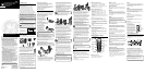
PARTS CHECKLIST
Make sure your package includes the items shown here.
DIGITAL SECURITY SYSTEM
Your cordless phone uses a digital security system to
provide protection against false ringing, unauthorized
access, and charges to your phone line.
When you place the handset in the base, the unit verifies
its security code. After a power outage or battery
replacement, you should place the handset in the base for
about 5 seconds to reset the code.
INSTALLATION
INSTALLATION OPTIONS
Although you can use your 2-line cordless telephone with
a single phone line, you must have two lines (separate
phone numbers) to use a two-line system. The following
diagrams show two possible setups:
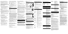
Two Lines on a Single Modular Jack
One type of two-line phone
system uses a single modular
jack which contains both phone
lines. Connect the phone cord
to the LINE 1/2 jack on the back
of the phone's base.
You must use a four conductor
telephone line cord like the one packed with your unit.
Each Line on a Separate Modular Jack
If you have two separate
phone jacks, each with its
own line, connect one of the
phone cord lines to the L2
jack on the back of the
phone's base and connect
the remaining phone line
cord to the LINE 1/2 jack on
the back of the phone's base.
NOTE : Connect the phone line cord from the LINE
1/2 jack on the back of the phone's base to the
modular phone jack you want to be line 1.
NOTE : Two-line capability requires two-line service
from your local telephone company.
A Single Line on a Separate Modular Phone Jack
If you want to only connect one line, plug one of the
telephone line cords into the LINE 1/2 jack and into a single
modular phone jack. Your phone will only use line 1 with
this connection. Line 2 will not be used.
DESKTOP INSTALLATION
NOTE : For desktop charging only, the handset is able
to charge facing up or down.
Two Lines on a Single Modular Jack
1. Remove the battery compartment door on the handset,
insert the battery pack, plug the cord into the jack (inside
the compartment), and replace the compartment door.
2. Set the RINGER switch (on the handset) to ON and
place the handset in the cradle on the base.
3. Plug one end of the telephone line cord into the LINE 1/2
jack on the base and the other end into a two-line
modular phone jack. For single line set up, see "A Single
Line on a Separate Modular Jack."
4. Plug one end of the power supply into the power jack on
the back of the base and the other end into an electrical
outlet. The "charge" indicator turns on, verifying the
battery is charging.
Allow the phone to charge for 12 hours prior to first use.
If you don't properly charge the phone, battery
performance will be compromised.
CAUTION: Use only the ATLINKS USA, Inc.
5-2530 power supply that came with this unit. Using
other power supplies may damage the unit.
WALL MOUNT INSTALLATION
Two Lines on a Single Modular Jack
Because it is necessary to charge the handset for 12 hours
prior to connecting the phone for use the first time, it is
better to leave the unit on a flat surface during initial
charge before attempting to hang it on the wall.
1. Remove the battery compartment door on the handset,
insert the battery pack, plug the cord into the jack (inside
the compartment), and replace the compartment door.
2. Set the RINGER switch (on the handset) to ON, and place
the handset in the cradle on the base.
3. Plug one end of the power supply into the jack on the
back of the phone’s base and the other end into an
electrical outlet. The CHARGE/IN USE indicator turns on
and indicates the battery is charging.
Allow the phone to charge for 12 hours prior to first
use. If you don’t properly charge the phone, battery
performance will be compromised.
CAUTION: Use only the ATLINKS USA, Inc.
5-2530 power supply that came with this unit. Using
other power supplies may damage the unit.
4. Remove the handset from the cradle and set aside. Turn
the base over and align the four slots on the bottom of
the base with the four hook-tabs on the mounting
bracket.
5. Insert the hook-tabs into the slots and push upwards
until the mounting bracket snaps securely into place.
6. Plug the telephone line cord into the jack marked
LINE 1/2 on the back of the phone’s base and the other
end into a two-line modular wall phone jack. For single-
line set up, see “A Single-Line on a Separate Modular
Jack.”
7. Slip the mounting holes (on the mounting bracket) over
the wall plate posts and slide the unit down firmly into
place. (Wall plate not included.)
8. Place the handset in the cradle.
NOTE: If desired, gather the extra telephone line and
power supply cord together, fasten with a wire tie, and
store inside the wall mounting bracket.
NOTE: The phone automatically defaults to touch-
tone dialing. To change to pulse (rotary) dialing, see
"Tone/Pulse Dialing." If you don't know which type of
service you have, check with the phone company.
Each Line on a Separate Modular Jack
Because it is necessary to charge the handset for 12 hours
prior to connecting the phone for use the first time, it is
better to leave the unit on a flat surface during initial
charge before attempting to hang it on the wall.
1. Remove the battery compartment door on the handset,
insert the battery pack, plug the cord into the jack (inside
the compartment), and replace the compartment door.
2. Set the RINGER switch (on the handset) to ON, and
place the handset in the cradle on the base.
3. Plug one end of the power supply into the jack on the
back of the phone’s base and the other end into an
electrical outlet. The CHARGE/IN USE indicator turns on
and indicates the battery is charging.
Allow the phone to charge for 12 hours prior to first use.
If you don’t properly charge the phone, battery
performance will be compromised.
CAUTION: Use only the ATLINKS USA, Inc.
5-2530 power supply that came with this unit. Using
other power supplies may damage the unit.
4. Remove the handset from the cradle and set aside. Turn
the base over and align the four slots on the bottom of the
base with the four hook-tabs on the mounting bracket.
5. Insert the hook-tabs into the slots and push upwards
until the mounting bracket snaps securely into place.
6. Plug the telephone line cord into the jack marked LINE 1/2
on the back of the phone’s base and the other end into a
two-line modular wall phone jack. Connect the remaining
phone cord to the L2 phone jack and into a single line
modular wall phone jack.
For single-line set up, see “A Single-Line on a Separate
Modular Jack.”
NOTE: The phone automatically defaults to touch-
tone dialing. To change to pulse (rotary) dialing, see
"Tone/Pulse Dialing." If you don't know which type of
service you have, check with the phone company.
7. Slip the mounting holes (on the mounting bracket) over
the wall plate posts and slide the unit down firmly into
place. (Wall plate not included.)
8. Place the handset in the cradle.
NOTE: If desired, gather the extra telephone line and
power supply cord together, fasten with a wire tie, and
store inside the wall mounting bracket.
SET UP
There are five programmable menus available: Language,
Area Code, Ringer Tone, Set Tone/Pulse, and Default
Setting.
LANGUAGE SETTING SELECTION
1. Press the flash/program button until “
1ENGLISH 2FRA
3ESP
“ shows in the display. “
1ENGLISH
“ is the default
setting.
2. Press 1,2, or 3 on the handset number pad or use the
CID review (up or down arrow) button to scroll to
your selection.
3. Press flash/program to store selection.
AREA CODE SELECTION
1. Press the flash/program button until
“AREA CODE - - -”
shows in the display. “
- - -”
is the default setting.
2. Use the handset number pad to enter your three digit
area code.
3. Press flash/program to store selection.
RINGER TONE SELECTION
1. LINE 1: press the flash/program button until “
SET
RINGER 1 1 2 3 4
” shows in the display. “
1
” is the
default setting.
LINE 2: press the flash/program button until “
SET
RINGER 2 1 2 3 4
” shows in the display. “
2
” is the
default setting.
2. Press 1, 2, 3 or 4 on the handset number pad or use the
CID review (up or down arrow) button to scroll to 1, 2, 3
or 4.
3. Press flash/program to store selection.
TONE/PULSE DIALING SELECTION
1. Press the flash/program button until “
SET TONE/PULSE
1 TONE 2PULSE”
shows in the display.
“1TONE”
is the
default setting.
2. Press 1 or 2 on the handset number pad or use the CID
review (up or down arrow) button to scroll to
1TONE
or
2PULSE
.
3. Press flash/program to store selection.
DEFAULT SETTING SELECTION
1. Press the flash/program button until
“DEFAULT.
SETTING.” 1YES 2NO
shows in the display.
“2NO”
is
the default setting.
2. Press 1 or 2 on the handset number pad or use the
CID Review (up or down arrow) button to scroll to
1YES
or
2NO
.
3. Press flash/program to store selection. You will hear a
confirmation tone.
CORDLESS PHONE BASICS
RECEIVING A CALL
1. Check the display to see who is calling.
2. Press the LINE 1 or LINE 2 button.
MAKING A CALL
To make a call, press the LINE 1 or LINE 2 button before
you dial and press it again to hang up.
PREVIEW DIALING
When you dial a number, it shows in the display for you to
preview first, then press the LINE 1 or LINE 2 button to dial
the number.
REDIAL
While the phone is on, press the redial/delete button to
redial the last number you dialed (up to 32 digits). If you
get a busy signal and want to keep dialing the number, just
press redial/delete again (you don't have to turn the phone
off and back on).
FLASH
Use the flash/program button to activate custom calling
services such as call waiting or call transfer, which
are available through your local phone company.
TIP: Don’t use the LINE 1 or LINE 2 button to
activate custom calling services such as call waiting, or
you’ll hang up the phone.
IN USE INDICATOR
The phone is ON when the indicator on the handset
antenna is lit and the L1 in use/vmwi or L2 in use/vmwi
indicator on the base is lit. The antenna indicator and the in
use indicators on the base flash when you receive a call.
CHANNEL BUTTON
While talking, you might need to manually change the
channel in order to get rid of static. Press and release the
chan button to advance to the next clear channel.
CONFERENCE
Press the hold button to place one line on hold. Press the
other line button, then dial the number of the second party.
Press the conf button. To disconnect, press the line button
you want to connect to or press cancel to disconnect both
lines.
TIP: You cannot receive Call Waiting Caller ID records
while in conference mode.
PAGING
To page the handset, press the page button on the phone’s
base. The handset will emit a page tone for 2 minutes and
“
PAGING
” shows in the display. To stop the page tone, press
any handset key or press the page button on the base.
TEMPORARY TONE
This feature enables pulse (rotary) service phone users to
access touch-tone services offered by banks, credit card
companies, etc., by pressing the tone button to temporarily
make the phone touch-tone compatible. To get information
about your bank account, for example, you would:
1. Call the bank’s information line.
2. Press the tone button (*) after your call is answered.
3. Follow the voice instructions to complete your transaction.
4. Hang up when finished. The phone returns to Pulse
(rotary) service.
27935
40-Channel Two Line 2.4 GHz Caller
ID with Call Waiting Caller ID
Cordless Telephone
User's Guide
We bring good things to life.
EQUIPMENT APPROVAL INFORMATION
Your telephone equipment is approved for connection to the Public
Switched Telephone Network and is in compliance with parts 15 and
68, FCC Rules and Regulations and the the Technical Requirements
for Telephone Terminal Equipment published by ACTA.
1 Notification to the Local Telephone Company
On the bottom of this equipment is a label indicating, among
other information, the US number and Ringer Equivalence
Number (REN) for the equipment. You must, upon request,
provide this information to your telephone company.
The REN is useful in determining the number of devices you
may connect to your telephone line and still have all of these
devices ring when your telephone number is called. In most (but
not all) areas, the sum of the RENs of all devices connected to
one line should not exceed 5. To be certain of the number of
devices you may connect to your line as determined by the REN,
you should contact your local telephone company.
Notes
• This equipment may not be used on coin service provided by the
telephone company.
• Party lines are subject to state tariffs, and therefore, you may not
be able to use your own telephone equipment if you are on a
party line. Check with your local telephone company.
• Notice must be given to the telephone company upon
permanent disconnection of your telephone from your line.
2 Rights of the Telephone Company
Should your equipment cause trouble on your line which may harm
the telephone network, the telephone company shall, where
practicable, notify you that temporary discontinuance of service may
be required. Where prior notice is not practicable and the
circumstances warrant such action, the telephone company may
temporarily discontinue service immediately. In case of such
temporary discontinuance, the telephone company must: (1) promptly
notify you of such temporary discontinuance; (2) afford you the
opportunity to correct the situation; and (3) inform you of your right to
bring a complaint to the Commission pursuant to procedures set forth
in Subpart E of Part 68, FCC Rules and Regulations.
The telephone company may make changes in its communications
facilities, equipment, operations or procedures where such action
is required in the operation of its business and not inconsistent
with FCC Rules and Regulations. If these changes are expected to
affect the use or performance of your telephone equipment, the
telephone company must give you adequate notice, in writing, to
allow you to maintain uninterrupted service.
ATLINKS USA, Inc.
10330 North Meridian Street
Indianapolis, IN 46290
© 2001 ATLINKS USA, Inc.
Trademark(s) ® Registered
Marca(s) ® Registrada(s)
Model 27935
15724410 (Rev. 0 DOM E)
01-39
Printed in China
MODULAR JACK REQUIREMENTS
You need an RJ11 type modular phone jack, which
is the most common type of phone jack and might
look like the one pictured here. If you don’t have a
modular jack, call your local phone company to
find out how to get one installed.
INSTALLATION NOTE: Some cordless telephones
operate at frequencies that may cause interference to
nearby TVs, microwave ovens, and VCRs. To minimize
or prevent such interference, the base of the cordless
telephone should not be placed near or on top of a
TV, microwave oven, or VCR. If such interference
continues, move the cordless telephone farther away
from these appliances. Certain other communications
devices may also use the 2.4 GHz frequency for
communication, and, if properly set, these devices may
interfere with each other and/or your new telephone.
If you are concerned with interference, please refer to
the owner’s manual for these devices on how to
properly set channels to avoid interference. Typical
devices that may use the 2.4 GHz frequency for
communication include wireless audio/video senders,
wireless computer networks, multi-handset cordless
telephone systems, and some long-range cordless
telephone systems.
SEE MARKING ON BOTTOM / BACK OF PRODUCT
RISK OF ELECTRIC SHOCK
DO NOT OPEN
WARNING: TO PREVENT FIRE OR
ELECTRICAL SHOCK HAZARD, DO
NOT EXPOSE THIS PRODUCT TO
RAIN OR MOISTURE.
THE LIGHTNING FLASH
AND ARROW HEAD
WITHIN THE TRIANGLE
IS A WARNING SIGN
ALERTING YOU OF
“DANGEROUS
VOLTAGE” INSIDE THE
PRODUCT.
CAUTION: TO REDUCE THE RISK OF
ELECTRIC SHOCK, DO NOT REMOVE
COVER (OR BACK). NO USER
SERVICEABLE PARTS INSIDE. REFER
SERVICING TO QUALIFIED SERVICE
PERSONNEL.
THE EXCLAMATION
POINT WITHIN THE
TRIANGLE IS A
WARNING SIGN
ALERTING YOU OF
IMPORTANT
INSTRUCTIONS
ACCOMPANYING THE
PRODUCT.
CAUTION:
Base
Handset
Mounting bracket
line 2
charge
PAGE
line 1
#
PAUSE
9
WXY Z
6
MNO
3
DEF
O
OPER
8
TUV
5
JKL
2
ABC
*
TONE
7
PQRS
4
GHI
1
CID
cha
n
f
la
s
h
p
r
o
g
r
a
m
mute
m
e
m
re
dia
l
c
a
n
c
e
l
h
o
l
d
conf
fo
rm
a
t
d
e
l
e
t
e
12
callback
c
a
ll
b
a
c
k
Belt clip
AC power
supply
Telephone
line cord
Handset battery
#
PAUSE
9
WXY Z
6
MNO
3
DEF
O
OPER
8
TUV
5
JKL
2
ABC
*
TON E
7
PQRS
4
GHI
1
CID
c
h
a
n
flash
p
r
o
g
r
a
m
mute
m
e
m
r
e
d
i
a
l
cancel
h
o
l
d
conf
f
o
r
m
a
t
d
e
l
e
t
e
12
c
a
l
l
b
a
c
k
c
a
l
l
b
a
c
k
1
2
6
7
3
5
3
4
2
1
#
PAUSE
9
WXYZ
6
MNO
3
DEF
O
OPER
8
TUV
5
JKL
2
ABC
*
TON E
7
PQRS
4
GHI
1
CID
c
h
a
n
flas
h
p
r
o
g
r
a
m
mute
m
e
m
r
e
d
i
a
l
c
an
cel
h
o
l
d
conf
f
o
r
m
a
t
d
e
l
e
t
e
12
c
a
l
l
b
a
c
k
c
a
l
l
b
a
c
k
2
1
3
7
6
5
#
PAUSE
9
WXYZ
6
MNO
3
DEF
O
OPER
8
TUV
5
JKL
2
AB C
*
TONE
7
PQRS
4
GHI
1
CID
c
h
a
n
f
la
s
h
p
r
o
g
r
a
m
mute
m
e
m
r
e
d
i
a
l
c
a
n
c
e
l
h
o
l
d
conf
f
o
r
m
a
t
d
e
l
e
t
e
12
c
a
l
l
b
a
c
k
c
a
llb
a
c
k
VOLUME buttons
CID
review
button
chan
button
flash/
program
button
Line 1/callback
button
redial/delete
button
TONE
button
mem
button
PAUSE
button
mute
button
RINGER
switch
cancel
button
hold/format
button
Line 2/callback
button
conf button
MUTE
Press the mute button to mute the microphone for private
conversations. The antenna indicator flashes when a call is
muted. Press the mute button again to resume your
telephone conversation.
HOLD
You can use the hold button to interrupt a conversation
without hanging up. To put a call on hold, press the hold
button.
HOLD
shows in the display. To release a line on
hold and resume a conversation, press the line button for
that call or pick up an extension phone.
CANCEL
Press the cancel button to cancel any command you
initiated. Press cancel to hang up after finishing a call.
RINGER SWITCH
The RINGER switch must be ON for the handset to ring
during incoming calls.
VOLUME
The VOLUME buttons control the volume of the
handset's earpiece.
VOICE MESSAGING
Provided your phone company
offers voice messaging service
and you subscribe to it, the L1
and L2 in use/vmwi indicators
on the base flash when the
phone is not in use to indicate
there is a message waiting. The
indicators stop flashing after the
message is reviewed.
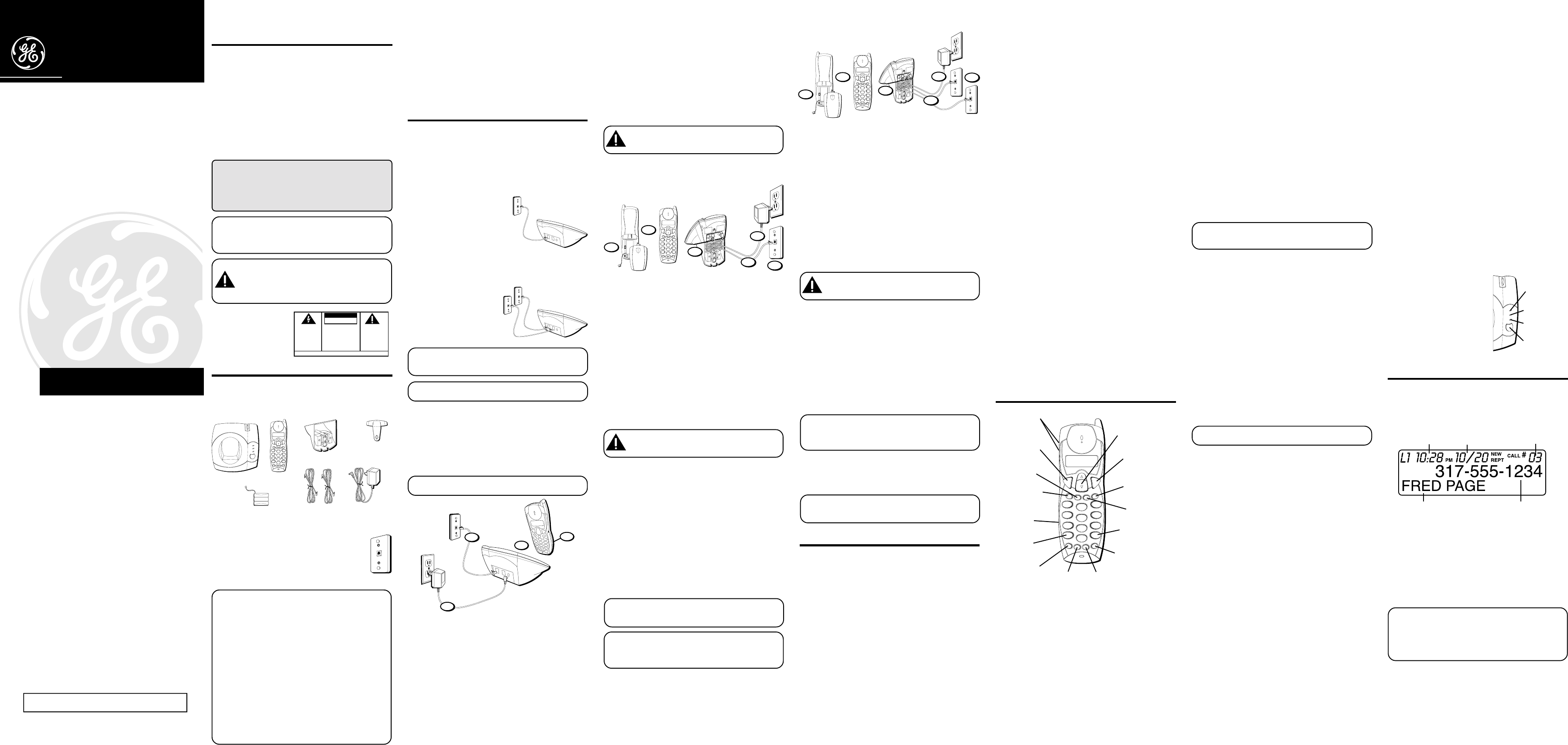
CALLER ID FEATURES
This unit receives and displays information transmitted by
your local phone company. This information can include
the phone number, date, and time;
or
the name, phone
number, date, and time. The unit can store up to 40 calls
for later review.
CALLER ID WITH CALL WAITING
Provided you subscribe to Caller ID with Call Waiting
service from your phone company, you are able to see who
is calling when you hear the call waiting beep. The caller
identification information appears in the display after you
hear the tone.
• Press the flash button to put the current person on hold
so that you can answer the incoming call.
IMPORTANT: In order to use the Caller ID functions
with this unit, you must subscribe to either the
standard Name/Number Caller ID Service or Caller
ID with Call Waiting Service. To know who is calling
while you are on the phone, you must subscribe to
Caller ID with Call Waiting Service.
line 2
charge
PAGE
line 1
line 2
indicator
charge/PAGE
indicator
PAGE
button
line 1
indicator
Caller ID name
Time
Date
Number of calls
Caller ID phone number
US NUMBER IS LOCATED ON THE CABINET BOTTOM
REN NUMBER IS LOCATED ON THE CABINET BOTTOM