


Part 5 – GPIO AT Commands Chapter 15 – GPIO AT Commands
Universal IP AT Commands Reference Guide (Document S000457K) 88
Chapter 15 – GPIO AT Commands
About GPIO
If the specific hardware allows GPIO (check availability with AT#GPIO=1), then you may specify certain external
events from the GPIOs to trigger specific stack functions; i.e., email, upload files, download files. In order for this
to work, you must configure the specific function first. For instance, if SENDMAIL1 will be called, then all
settings pertaining to SENDMAIL1 must be configured before the #GPIO command is configured.
Note:
MultiModem iCell: The MultiModem iCell allows for the following GPIO IDs and GPIO function combinations:
GPIO 1 - 2: GPIO function 0 may be selected
GPIO 3 - 4: GPIO functions 0, 1, 2 and 3 may be selected
GPIO 5: GPIO function 3 may be selected
SocketModem iCell: The SocketModem iCell allows for the following GPIO IDs and GPIO function combinations:
GPIO 1 - 2: GPIO function 0 may be selected
GPIO 3 - 4: GPIO functions 0, 1, 2 and 3 may be selected
GPIO 5: GPIO 5 is non-functional
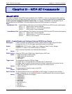
#GPIO – Enable/Disable and Configure External GPIO Driven Events
Description: If GPIO is enabled and configured correctly, a specific external trigger (Digital HI/LOW or
Analog value from 0-3.3V) will trigger a specified function from the stack.
Syntax: AT#GPIO=ID, GPIO Function, Trigger Level, Debounce, Stack Function, Hangup
AT#GPIO=<n> where n is the GPIO number or AT#VALL
ID: GPIO number as described in the hardware documentation
Values: 1 - 5
GPIO Function: Allows the GPIO to be a Digital Input, Digital Output or ADC input
Values: 0 - Digital Input without internal pullup
1 - Digital Input with internal pullup
2 - Digital Output
3 - ADC input
Trigger Level: The Voltage level at which GPIO will trigger.
For Digital input, a value greater than 0 indicates high. 0 indicates low.
For Digital output, a positive value will drive the line high. A zero value will drive the line low.
For ADC input, the trigger value will be in the range of 0 to 3300 millivolts.
Values: 0 - 3300 in milliVolts
Debounce: The time between successive reads on the GPIO.
Values: 0 - 65535 milliseconds
Stack Function: The desired stack function to be specified on a GPIO trigger. The stack function must be
properly configured; i.e., for a sendmail function, all proper sendmail items must be configured.
Values: 0 - Disabled (The GPIO will not trigger)
1 - #SENDMAIL1
2 - #SENDMAIL2
3 - #SENDMAIL3
4 - #PUTMAIL
5 - #GETMAIL
6 - #LTCPSTART=1
7 - #OTCP=1
8 - #OUDP=1
9 - #LUDPSTART=1