


J.H. • 3-92 • © Honeywell Inc. 1992 • Form Number 69-0348—1
T8611G,R
Chronotherm III
Fuel Saver Thermostats
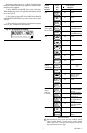
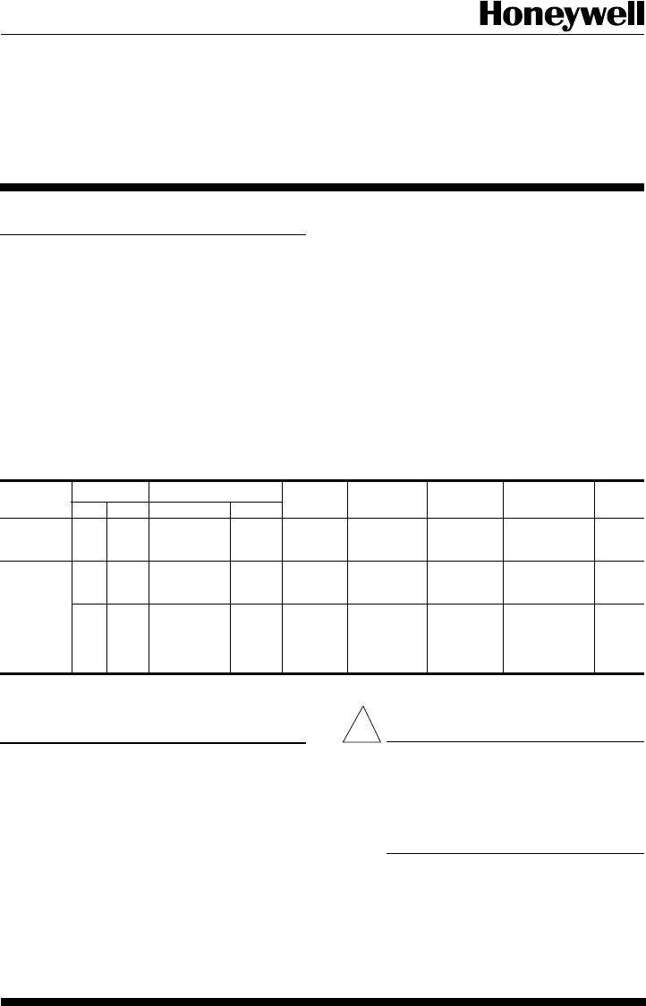
TABLE 1—Thermostat Models.
Thermostat Stages Switching LEDs Changeover Terminals Comments See Fig.
Heat Cool System Fan
T8611G 2 1 EM.HEAT- ON- EM.HT, Auto R, C/X, L, — 4
HEAT-OFF- AUTO AUX.HT. W
2
,E,G,O,
AUTO-COOL B,Y,X
2
,X
1
T8611R 2 1 EM.HEAT- ON- EM.HT., Manual R,C/X,L, — 5
HEAT-OFF- AUTO AUX.HT. W
2
,E,W
1
,G,
COOL O,B,Y,P
21EM.HEAT- ON- EM.HT. Manual R,B,X,W
2
, Exact 6
HEAT-OFF- AUTO E,W
1
,G,O, replacement
COOL H,Y
1
for York
model no.
2ET11700224.
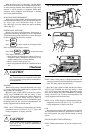
Installation
WHEN INSTALLING THIS PRODUCT...
1. Read these instructions carefully. Failure to allow
them could damage the product or cause a hazardous condi-
tion.
2. Check the ratings on the product to make sure the
product is suitable for your application.
3. Installer must be a trained, experienced service techni-
cian.
4. Allow thermostat to warm to room temperature before
operating.
5. After installation is complete, check out product op-
eration as provided in these instructions.
CAUTION
1. Disconnect power supply to prevent electri-
cal shock or equipment damage.
2. After wiring is complete, push excess wire
back into the hole, and plug hole with
nonhardening caulk, putty or insulation to
prevent drafts from affecting thermostat op-
eration.
LOCATION
Install thermostat and subbase about 5 ft. [1.5m] above the
floor in an area with good air circulation at room temperature.
Do not install the thermostat where it may be affected
!
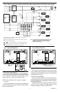
Application
These thermostats provide energy saving control for a 24
Vac multistage heat pump heating/cooling system as indi-
cated in Table 1 and are powered directly from the control
transformer. All models have 5-1-1 programming.
As long as AC power is continuously available to trans-
former, the thermostat will be compatible with most control
systems.
The T8611G,R models include SYSTEM and ENRG
SAV LEDs near the top front of the thermostat. The SYS-
TEM LED lights when the thermostat is signaling for heating
or air conditioning. The ENGR SAV LED lights during the
LEAVE and SLEEP periods.
The AUX. HT., EM. HT., and CHECK LEDS are located
near the bottom center of the subbase. See Table 1. The AUX.
HT. LED lights whenever the thermostat is calling for
operation of the backup or auxiliary heater. Backup (auxil-
iary) heat is more expensive to operate than the heat pump and
typically is used only when the heat pump is unable to handle
the load. The EM. HT. LED lights whenever the thermostat
system switch is in the EM. HT. position. The CHECK LED
lights when something needs to be checked to maintain
efficient operation of the system. Consult heat pump equip-
ment literature to determine specific meaning of this LED.
Heat and cool anticipation is fixed in all models; no
adjustment is necessary. Cycle rates are adjustable for auxil-
iary heating stage.
TRADELINE