29480
10-Number Memory
Two-Line Telephone
User’s Guide
EQUIPMENT APPROVAL INFORMATION
Your telephone equipment is approved for connection to the Public Switched Telephone Network and is in
compliance with parts 15 and 68, FCC Rules and Regulations and the Technical Requirements for
Telephone Terminal Equipment published by ACTA.
1 Notification to the Local Telephone Company
On the bottom of this equipment is a label indicating, among other information, the US number
and Ringer Equivalence Number (REN) for the equipment. You must, upon request, provide this
information to your telephone company.
The REN is useful in determining the number of devices you may connect to your telephone line and
still have all of these devices ring when your telephone number is called. In most (but not all) areas, the
sum of the RENs of all devices connected to one line should not exceed 5. To be certain of the number of
devices you may connect to your line as determined by the REN, you should contact your local telephone
company.
A plug and jack used to connect this equipment to the premises wiring and telephone network must comply
with the applicable FCC Part 68 rules and requirements adopted by the ACTA. A compliant telephone cord
and modular plug is provided with this product. It is designed to be connected to a compatible modular
jack that is also compliant. See installation instructions for details.
Notes
• This equipment may not be used on coin service provided by the telephone company.
• Party lines are subject to state tariffs, and therefore, you may not be able to use your own
telephone equipment if you are on a party line. Check with your local telephone company.
• Notice must be given to the telephone company upon permanent disconnection of your telephone
from your line.
• If your home has specially wired alarm equipment connected to the telephone line, ensure the
installation of this product does not disable your alarm equipment. If you have questions about
what will disable alarm equipment, consult your telephone company or a qualified installer.
2 Rights of the Telephone Company
Should your equipment cause trouble on your line which may harm the telephone network, the telephone
company shall, where practicable, notify you that temporary discontinuance of service may be required.
Where prior notice is not practicable and the circumstances warrant such action, the telephone company
may temporarily discontinue service immediately. In case of such temporary discontinuance, the
telephone company must: (1) promptly notify you of such temporary discontinuance; (2) afford you the
opportunity to correct the situation; and (3) inform you of your right to bring a complaint to the Commission
pursuant to procedures set forth in Subpart E of Part 68, FCC Rules and Regulations.
The telephone company may make changes in its communications facilities, equipment, operations
or procedures where such action is required in the operation of its business and not inconsistent
with FCC Rules and Regulations. If these changes are expected to affect the use or performance of
your telephone equipment, the telephone company must give you adequate notice, in writing, to
allow you to maintain uninterrupted service.
We bring good things to life.
INTERFERENCE INFORMATION
This device complies with Part 15 of the FCC Rules. Operation is subject to the following two conditions: (1) This device
may not cause harmful interference; and (2) This device must accept any interference received, including interference
that may cause undesired operation.
This equipment has been tested and found to comply with the limits for a Class B digital device, pursuant to Part 15 of the
FCC Rules. These limits are designed to provide reasonable protection against harmful interference in a residential
installation.
This equipment generates, uses, and can radiate radio frequency energy and, if not installed and used in accordance
with the instructions, may cause harmful interference to radio communications. However, there is no guarantee that
interference will not occur in a particular installation.
If this equipment does cause harmful interference to radio or television reception, which can be determined by turning
the equipment off and on, the user is encouraged to try to correct the interference by one or more of the following
measures:
• Reorient or relocate the receiving antenna (that is, the antenna for radio or television that is “receiving” the
interference).
• Reorient or relocate and increase the separation between the telecommunications equipment and receiving
antenna.
• Connect the telecommunications equipment into an outlet on a circuit different from that to which the receiving
antenna is connected.
If these measures do not eliminate the interference, please consult your dealer or an experienced radio/television
technician for additional suggestions. Also, the Federal Communications Commission has prepared a helpful booklet,
“How To Identify and Resolve Radio/TV Interference Problems.” This booklet is available from the U.S. Government
Printing Office, Washington, D.C. 20402. Please specify stock number 004-000-00345-4 when ordering copies.
HEARING AID COMPATIBILITY
This telephone system meets FCC standards for Hearing Aid Compatibility.
BEFORE YOU BEGIN
PARTS CHECKLIST
Make sure your package includes the following items:
MODULAR JACK REQUIREMENTS
To properly connect your phone to your telephone lines, you should identify
the type of wall jack(s) you have. You will need an RJ11C (for a single line) or
a RJ14C (for two lines) type modular phone jack, which might look like the
one pictured here. If you don’t have either modular jack, call your local
phone company to find out how to get one installed.
CAUTION: When using telephone equipment, there are basic safety
instructions that should always be followed. Refer to the IMPOR-
TANT SAFETY INSTRUCTIONS provided with this product and
save them for future reference.
INSTALLATION & SETUP
IMPORTANT INSTALLATION INFORMATION
• Never install telephone wiring during a lightning storm.
• Never touch non-insulated telephone wires or terminals, unless the telephone line
has been disconnected at the network interface.
• Use caution when installing or modifying telephone lines.
• Never install telephone jacks in wet locations unless the jack is specifically
designed for wet locations.
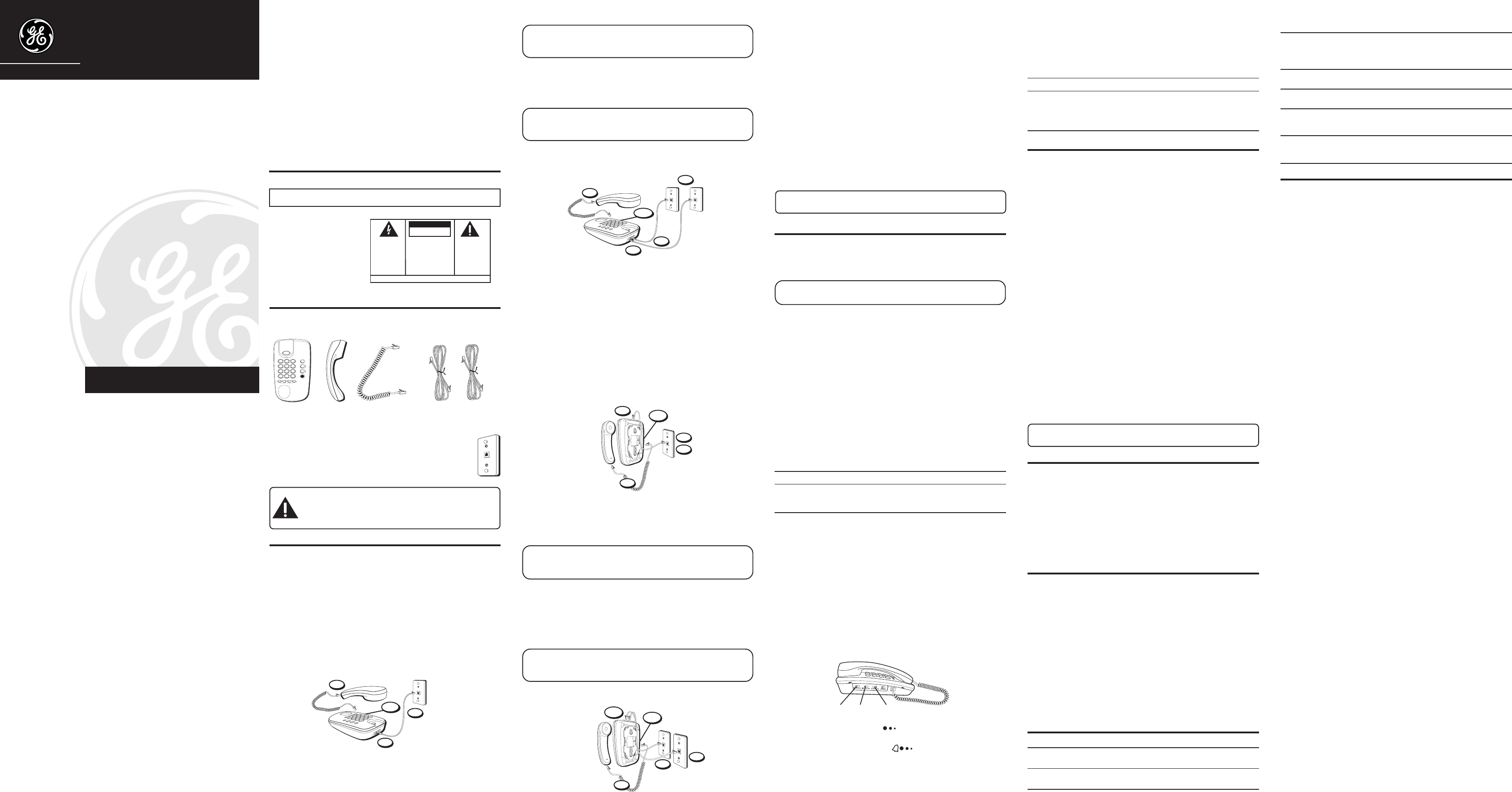
DESKTOP INSTALLATION
Your two-line phone should be placed on a level surface such as a tabletop or
desk.
Connecting Lines 1+2 to One Dual-Line Phone Jack
1. Connect one end of either straight telephone line cord to the jack marked LINE 1+2
on the back of the base.
Model 29480B
00000952 (Rev. 1 E/S)
04-48
Printed in China
ATLINKS USA, Inc.
101 W. 103rd Street
Indianapolis, IN 46290
© 2004 ATLINKS USA, Inc.
Trademark(s) ® Registered
Marca(s) Registrada(s)
SEE MARKING ON BOTTOM / BACK OF PRODUCT
RISK OF ELECTRIC SHOCK
DO NOT OPEN
WARNING: TO PREVENT FIRE OR
ELECTRICAL SHOCK HAZARD, DO
NOT EXPOSE THIS PRODUCT TO
RAIN OR MOISTURE.
THE LIGHTNING FLASH
AND ARROW HEAD
WITHIN THE TRIANGLE
IS A WARNING SIGN
ALERTING YOU OF
“DANGEROUS
VOLTAGE” INSIDE THE
PRODUCT.
CAUTION: TO REDUCE THE RISK OF
ELECTRIC SHOCK, DO NOT REMOVE
COVER (OR BACK). NO USER
SERVICEABLE PARTS INSIDE. REFER
SERVICING TO QUALIFIED SERVICE
PERSONNEL.
THE EXCLAMATION
POINT WITHIN THE
TRIANGLE IS A
WARNING SIGN
ALERTING YOU OF
IMPORTANT
INSTRUCTIONS
ACCOMPANYING THE
PRODUCT.
CAUTION:
US NUMBER IS LOCATED ON THE CABINET BOTTOM
REN NUMBER IS LOCATED ON THE CABINET BOTTOM
A
B
C
2
D
E
F
3
1
J
K
L
5
M
N
O
6
G
H
I
4
T
U
V
8
W
X
Y
Z
9
P
Q
R
S
7
O
P
E
R
0
#
T
O
N
E
*
2
1
L
I
N
E
L
IN
E
H
O
L
D
C
O
N
F
E
R
E
N
C
E
Base Handset
Handset cord
Two 4-wire telephone
line cords
2. Connect the other end of the straight white telephone line cord to a dual-line wall jack.
NOTE: If you connect the telephone line cord to a single-line (RJ11C) wall
phone jack, you will only be able to use one telephone line (either LINE 1 or
LINE 2) but not both lines simultaneously.
3. Connect one end of the coiled handset cord to the jack on the side of the base and
connect the other end to the jack at the bottom of the handset, then place the
handset in the cradle.
4. Set the RINGER 1 and RINGER 2 volume switches to the desired listening level ( HI,
LO or OFF).
NOTE: When in OFF position that line will not ring. Your telephone has
separate and distinct ringer sounds for each line this will allow you to
determine (audibly) the line of an incoming call.
5. Set the mode switch to TONE. If you have problems dialing switch to PULSE.
Connecting Lines 1+2 to Two Single-Line Wall Jacks
1. Plug one end of a straight white telephone line to the jack marked LINE 1+2 on the
back of the base.
2. Plug one end of the other straight white telephone line to the jack marked LINE 2 on
the back of the base.
3. Connect the other end of each straight white telephone line cord to the two single
line wall phone jacks.
4. Connect one end of the coiled handset cord to the jack on the side of the base and
connect the other end to the jack at the bottom of the handset, then place the
handset in the cradle.
5. Set the RINGER 1 and RINGER 2 volume switches to HI, LO, or OFF.
6. Set the dialing mode switch to TONE. If you have problems dialing, switch to
PULSE.
WALL MOUNT INSTALLATION
Your telephone can also be mounted on a wall plate (not included).
Connecting Lines 1+2 to One Dual-Line Phone Jack
1. Connect one end of either straight telephone line cord to the jack marked LINE 1+2
on the back of the base.
2. Connect the other end of the straight white telephone line cord to a dual-line wall
jack.
NOTE: If you connect the telephone line cord to a single-line (RJ11C) wall
phone jack, you will only be able to use one telephone line (either LINE 1 or
LINE 2) but not both lines simultaneously.
3. Slip the mounting holes on the base over the wall plate posts and firmly slide the
unit down into place (wall plate not included).
4. Connect one end of the coiled handset cord to the jack on the side of the base and
connect the other end to the jack at the bottom of the handset, then place the
handset in the cradle.
5. Set the RINGER 1 and RINGER 2 volume switches to the desired listening level ( HI,
LO or OFF).
NOTE: When in OFF position that line will not ring. Your telephone has
separate and distinct ringer sounds for each line this will allow you to
determine (audibly) the line of an incoming call.
6. Set the dialing mode switch to TONE. If you have problems dialing switch to PULSE.
Connecting Lines 1+2 to Two Single-Line Wall Jacks
1. Plug one end of a straight white telephone line to the jack marked LINE 1+2 on the
back of the base.
2. Plug one end of the other straight white telephone line to the jack marked LINE 2 on
the back of the base.
3. Connect the other end of each straight white telephone line cord to the two single
line wall phone jacks.
4. Slip the mounting holes on the base over the wall plate posts and firmly slide the
unit down into place (wall plate not included).
5. Connect one end of the coiled handset cord to the jack on the side of the base and
connect the other end to the jack at the bottom of the handset, then place the
handset in the cradle.
6. Set the RINGER 1 and RINGER 2 volume switches to the desired listening level (HI,
LO, or OFF).
7. Set the dialing mode switch to TONE. If you have problems dialing, switch to
PULSE.
WRAPPING THE TELEPHONE LINE CORD
In desktop or wallmount mode, you may want to wrap the excess telephone line cord
around the mounting bracket on the bottom of the base.
NOTE: For best results, use a short line cord (not included), which can be
purchased at most electronics specialty stores or department stores.
TELEPHONE BASICS
MAKING AND RECEIVING CALLS
CHOOSE A LINE
Press LINE 1 or LINE 2.
NOTE: You can use the telephone if you have only one incoming line.
However you cannot access a second line.
REDIAL
Use REDIAL, to quickly redial the last number that was manually dialed. This is useful
when a line is busy for a long time.
1. Pick up the handset.
2. Wait for dial tone.
3. Press the REDIAL button. The phone automatically redials the last number that was
dialed (up to 32 digits).
FLASH
Press the FLASH button to activate custom calling services such as call waiting or call
transfer, which are provided by your local phone company. Do not use the hook switch
because you might hang up the phone.
HOLD
Press HOLD button and hang up the handset. The LINE indicator lights to indicate the
party is on hold.
TO CONTINUE THE CONVERSATION:
At this phone From another phone
1. Pick up handset. 1. Pick up handset.
2. Press LINE on hold.
CONFERENCE
The conference feature enables you to carry on three-way conversation using LINES 1
and 2 simultaneously.
1. Place first party on HOLD.
2. Press the alternate LINE.
3. Dial phone number for second party.
4. Press CONF and talk to both parties.
5. When finished with conference press LINE 1 or 2 to talk privately and disconnect
other line.
6. When finished hang up.
VOLUME
The volume controls for the handset and line ringers are separate on this phone so you
can adjust one without affecting the others.
To adjust the handset volume, use the VOL
switch on the left side of the phone.
To adjust RINGER 1 and RINGER 2 volumes, use the switches on the left side of the
base unit . To select volume for RINGER use
OFF. Note that, if in the OFF
position, that line will not ring. Your telephone has separate and distinct ringer sounds
for each line allowing you to determine (audibly) the line of an incoming call.
TEMPORARY TONE FEATURE
If you have Pulse (rotary) service, and want to access customer calling services that
require tone dialing, such as getting information from a local bank, you can use this feature.
1. Press the TONE BUTTON (*) after you have connected to the service to enable Tone dialing.
2. When you hang up, the phone automatically returns to Pulse dialing mode.
To Make a Call To Receive a Call
1. Pick up the handset. 1. Press the line number of the flashing
2. Press LINE 1 or LINE 2. indicator.
3. Replace the handset to hang up. 2. Pick up the handset.
3. Replace the handset to hang up.
MEMORY
Store as many as 10 numbers in memory for easy dialing. Each of the memory buttons
is capable of storing phone numbers that are up to 16 digits.
STORING A NUMBER IN MEMORY
1. Pick up the handset.
2. Select line 1 or 2, and wait for a dial tone.
3. Press STORE button.
4. Enter the telephone number to be stored.
5. Press STORE button.
6. Press the desired memory location button (0-9 on the keypad).
7. Replace the handset.
8. To store another number repeat steps 1-7.
INSERTING A PAUSE IN THE DIALING SEQUENCE
Press the REDIAL button to insert a delay in the dialing sequence of a stored telephone
number when a pause is needed to wait for a dial tone (for example after you dial 9 for an
outside line, or to wait for a computer access tone). Each pause counts as 1 digit in the
dialing sequence.
CHANGING A STORED NUMBER
To change a stored number, you just replace it with a different number using the
procedure for storing a number.
DIALING A STORED NUMBER
1. Pick up the handset.
2. Press the line you want (line 1 or line 2).
3. Wait for a dial tone.
4. Press MEM DIAL button.
5. Press memory address button 1-9.
NOTE: If you make a mistake while storing a number, hang up and repeat
the storing procedure.
GENERAL PRODUCT CARE
To keep your Telephone working and looking good, follow these guidelines:
• Avoid putting it near heating appliances and devices that generate electrical noise
(for example, motors or fluorescent lamps).
• DO NOT expose to direct sunlight or moisture.
• Avoid dropping the unit and/or other rough treatment.
• Clean with a soft cloth.
• Never use a strong cleaning agent or abrasive powder because this will damage
the finish.
• Retain the original packaging in case you need to ship it at a later date.
SERVICE
This product may be serviced only by the manufacturer or its authorized service
agents. Changes or modifications not expressly approved by ATLINKS USA, Inc. could
void the user’s authority to operate this product. For instructions on how to obtain
service, refer to the warranty included in this guide or call customer service at 1-800-
448-0329.
Or refer inquiries to:
ATLINKS USA, Inc.
Manager, Consumer Relations
P O Box 1976
Indianapolis, IN 46206
Attach your sales receipt to the booklet for future reference or jot down the date this
product was purchased or received as a gift. This information will be valuable if
service should be required during the warranty period.
Purchase date ________________________________________________
Name of store ________________________________________________
TROUBLESHOOTING TIPS
Problem Solution
No dial tone. • Check hook switch to make sure it pops up.
• Check if a LINE button depressed.
Phone dials in pulse with tone service • Make sure TONE/PULSE switch is set to TONE
Phone won’t dial out with pulse service • Make sure TONE/PULSE switch is set to PULSE
Phone doesn’t ring • Check RINGER VOLUME.
• You might have too many phones on one line.
Can’t be heard by • Make sure phone line is connected properly.
other party • Make sure other phones are not OFF hook at the
same time. If so, this is normal condition as volume
drops when additional phones are used at once.
Memory dialing • Make sure you entered numbers correctly. (See
“Memory.”)
Indicator lights do not • Check all of the phones on this line.
Turn on or off properly • Switch the line cord jacks for lines 1 and 2.
While dialing with Tone Service, the • Check the Tone/Pulse switch. If in PULSE
phone makes clicking sounds and line position, set to TONE, then hang up and
indicators (lights) flicker on and off. dial again.
Both line buttons are down and both • Press Line 1 or Line 2 to select the line you
lines are active (a dial tone can want to use. The other line button releases.
be heard).
LIMITED WARRANTY
What your warranty covers:
• Defects in materials or workmanship.
For how long after your purchase:
• One year, from date of purchase.
(The warranty period for rental units begins with the first rental or 45 days from date
of shipment to the rental firm, whichever comes first.)
What we will do:
• Provide you with a new or, at our option, a refurbished unit. The exchange unit is under
warranty for the remainder of the original product’s warranty period.
How you get service:
• Properly pack your unit. Include any cables, etc., which were originally provided
with the product.
• ”Proof of purchase in the form of a bill of sale or receipted invoice which is evidence
that the product is within the warranty period, must be presented to obtain warranty
service.” For rental firms, proof of first rental is also required. Also print your name and
address and a description of the defect. Send via standard UPS or its equivalent to:
ATLINKS USA, Inc.
c/o Thomson
11721 B Alameda Ave.
Socorro, Texas 79927
• Pay any charges billed to you by the Exchange Center for service not covered by the
warranty.
• Insure your shipment for loss or damage. ATLINKS accepts no liability in case of
damage or loss.
• A new or refurbished unit will be shipped to you freight prepaid.
What your warranty
does not
cover:
• Customer instruction. (Your Owner’s Manual provides information regarding
operating instructions and user controls. Any additional information, should be
obtained from your dealer.)
• Installation and setup service adjustments.
• Batteries.
• Damage from misuse or neglect.
• Products which have been modified or incorporated into other products.
• Products purchased or serviced outside the USA.
• Acts of nature, such as but not limited to lightning damage.
Limitation of Warranty:
• THE WARRANTY STATED ABOVE IS THE ONLY WARRANTY APPLICABLE TO THIS
PRODUCT. ALL OTHER WARRANTIES, EXPRESS OR IMPLIED (INCLUDING ALL
IMPLIED WARRANTIES OF MERCHANTABILITY OR FITNESS FOR A PARTICULAR
PURPOSE) ARE HEREBY DISCLAIMED. NO VERBAL OR WRITTEN INFORMATION
GIVEN BY ATLINKS USA, INC., ITS AGENTS, OR EMPLOYEES SHALL CREATE A
GUARANTY OR IN ANY WAY INCREASE THE SCOPE OF THIS WARRANTY.
• REPAIR OR REPLACEMENT AS PROVIDED UNDER THIS WARRANTY IS THE EXCLUSIVE
REMEDY OF THE CONSUMER. ATLINKS USA, INC. SHALL NOT BE LIABLE FOR
INCIDENTAL OR CONSEQUENTIAL DAMAGES RESULTING FROM THE USE OF THIS
PRODUCT OR ARISING OUT OF ANY BREACH OF ANY EXPRESS OR IMPLIED
WARRANTY ON THIS PRODUCT. THIS DISCLAIMER OF WARRANTIES AND LIMITED
WARRANTY ARE GOVERNED BY THE LAWS OF THE STATE OF INDIANA. EXCEPT TO
THE EXTENT PROHIBITED BY APPLICABLE LAW, ANY IMPLIED WARRANTY OF
MERCHANTABILITY OR FITNESS FOR A PARTICULAR PURPOSE ON THIS PRODUCT IS
LIMITED TO THE APPLICABLE WARRANTY PERIOD SET FORTH ABOVE.
How state law relates to this warranty:
• Some states do not allow the exclusion nor limitation of incidental or consequential
damages, or limitations on how long an implied warranty lasts so the above
limitations or exclusions may not apply to you.
• This warranty gives you specific legal rights, and you also may have other rights
that vary from state to state.
If you purchased your product outside the USA:
• This warranty does not apply. Contact your dealer for warranty information.
1
2
3
4/5
1
2
3
4
5/6
3
2
4
5/6
1
4
3
5
6/7
1/2
volume
switch
ringer1
switch
ringer2
switch


