DESKTOP INSTALLATION
A coiled handset cord and two
straight telephone line cords are
packaged with your unit. One of the
telephone line cords is in the carton;
the other is located on the cord wrap
inside the adapter.
TELEPHONE OPERATION
CHOOSE A LINE
• Press LINE 1 or LINE 2. When the handset is off hook, an indicator lights
above the button indicating the line is in use.
2-9420
12-Number Memory
Two-Line Telephone
User’s Guide
FCC REGISTRATION INFORMATION
Your GE telephone equipment is registered with the Federal Communications Commission and is in compliance with parts 15
and 68, FCC Rules and Regulations.
1 Notification to the Local Telephone Company
On the bottom of this equipment is a label indicating, among other information, the FCC Registration number and Ringer
Equivalence Number (REN) for the equipment. You must, upon request, provide this information to your telephone company.
The REN is useful in determining the number of devices you may connect to your telephone line and still have all of these
devices ring when your telephone number is called. In most (but not all) areas, the sum of the RENs of all devices
connected to one line should not exceed 5. To be certain of the number of devices you may connect to your line as
determined by the REN, you should contact your local telephone company.
Notes
• This equipment may not be used on coin service provided by the telephone company.
• Party lines are subject to state tariffs, and therefore, you may not be able to use your own telephone equipment if you
are on a party line. Check with your local telephone company.
• Notice must be given to the telephone company upon permanent disconnection of your telephone from your line.
2 Rights of the Telephone Company
Should your equipment cause trouble on your line which may harm the telephone network, the telephone company shall,
where practicable, notify you that temporary discontinuance of service may be required. Where prior notice is not
practicable and the circumstances warrant such action, the telephone company may temporarily discontinue service
immediately. In case of such temporary discontinuance, the telephone company must: (1) promptly notify you of such
temporary discontinuance; (2) afford you the opportunity to correct the situation; and (3) inform you of your right to bring a
complaint to the Commission pursuant to procedures set forth in Subpart E of Part 68, FCC Rules and Regulations.
The telephone company may make changes in its communications facilities, equipment, operations of procedures where
such action is required in the operation of its business and not inconsistent with FCC Rules and Regulations. If these
changes are expected to affect the use or performance of your telephone equipment, the telephone company must give
you adequate notice, in writing, to allow you to maintain uninterrupted service.
INTERFERENCE INFORMATION
This device complies with Part 15 of the FCC Rules. Operation is subject to the following two conditions: (1) This device may not
cause harmful interference; and (2) This device must accept any interference received, including interference that may cause
undesired operation.
This equipment has been tested and found to comply with the limits for a Class B digital device, pursuant to Part 15 of the FCC
Rules. These limits are designed to provide reasonable protection against harmful interference in a residential installation.
This equipment generates, uses, and can radiate radio frequency energy and, if not installed and used in accordance with the
instructions, may cause harmful interference to radio communications. However, there is no guarantee that interference will
not occur in a particular installation.
If this equipment does cause harmful interference to radio or television reception, which can be determined by turning the
equipment off and on, the user is encouraged to try to correct the interference by one or more of the following measures:
• Reorient or relocate the receiving antenna (that is, the antenna for radio or television that is “receiving” the interference).
• Reorient or relocate and increase the separation between the telecommunications equipment and receiving antenna.
• Connect the telecommunications equipment into an outlet on a circuit different from that to which the receiving antenna is
connected.
• Consult the dealer or an experienced radio/TV technician for help.
If these measures do not eliminate the interference, please consult your dealer or an experienced radio/television technician
for additional suggestions. Also, the Federal Communications Commission has prepared a helpful booklet, “How To Identify and
Resolve Radio/TV Interference Problems.” This booklet is available from the U.S. Government Printing Office, Washington, D.C.
20402. Please specify stock number 004-000-00345-4 when ordering copies.
HEARING AID COMPATIBILITY
This telephone system meets FCC standards for Hearing Aid Compatibility.
Model 2-9420C
XXXXXXXX (Rev. 0 E/S)
97-45
Printed in XXXXXXX
INSTALL THE BATTERIES
BATTERIES FOR SUPPLEMENTARY POWER
Four ‘AA’-size alkaline batteries (not included) provide power for LINE 1 and
LINE 2 indicator lights. If you want the LINE indicators to light when another
phone is off the hook, install the optional batteries.
1. If telephone is wall mounted, remove from
mounting.
2. Unplug modular jack from the phone wall outlet.
3. Slide memory directory tray up and off phone to
expose battery compartment door.
4. Slide flat blade screwdriver down between the
cabinet and top of door and snap open door.
Remove battery door.
5. Install 4 ‘AA’-size batteries as indicated on the
diagram in the battery compartment.
Note: If using phone for one line operation only,
then insert just the bottom 2 batteries (those
closest to the emergency/quick dial locations).
6. Replace door, and directory tray.
7. Plug the phone into modular jack.
BATTERIES FOR BACKUP MEMORY
A consumer replaceable long-life lithium battery
(3V) is installed in the phone to provide back-up
power for retaining numbers in memory. The lithium
battery compartment is located on the bottom of the
telephone base.
1. If telephone is wall mounted, remove from
mounting.
2. Unplug modular jack from the phone wall outlet.
3. Remove adapter to expose battery compartment.
4. Using a pointed object open the battery door and
remove.
5. Insert a pointed object, in opening at either end
of the battery cartridge and lift up.
6. Slide battery cartridge out and dispose of
immediately.
7. Insert replacement battery cartridge and snap
into place .The battery cartridge can be inserted
only one way. Replace door.
8. Replace adapter.
9. Plug the phone into modular jack.
10. You may have to reprogram some or all of the
number into memory.
BATTERY SAFETY PRECAUTIONS
• Don’t disassemble, mutilate, puncture, wet, or dispose of battery in fire.
Like other batteries of this type, if it is burned or punctured, it could
release toxic materials which can cause injury.
• Keep batteries out of the reach of children.
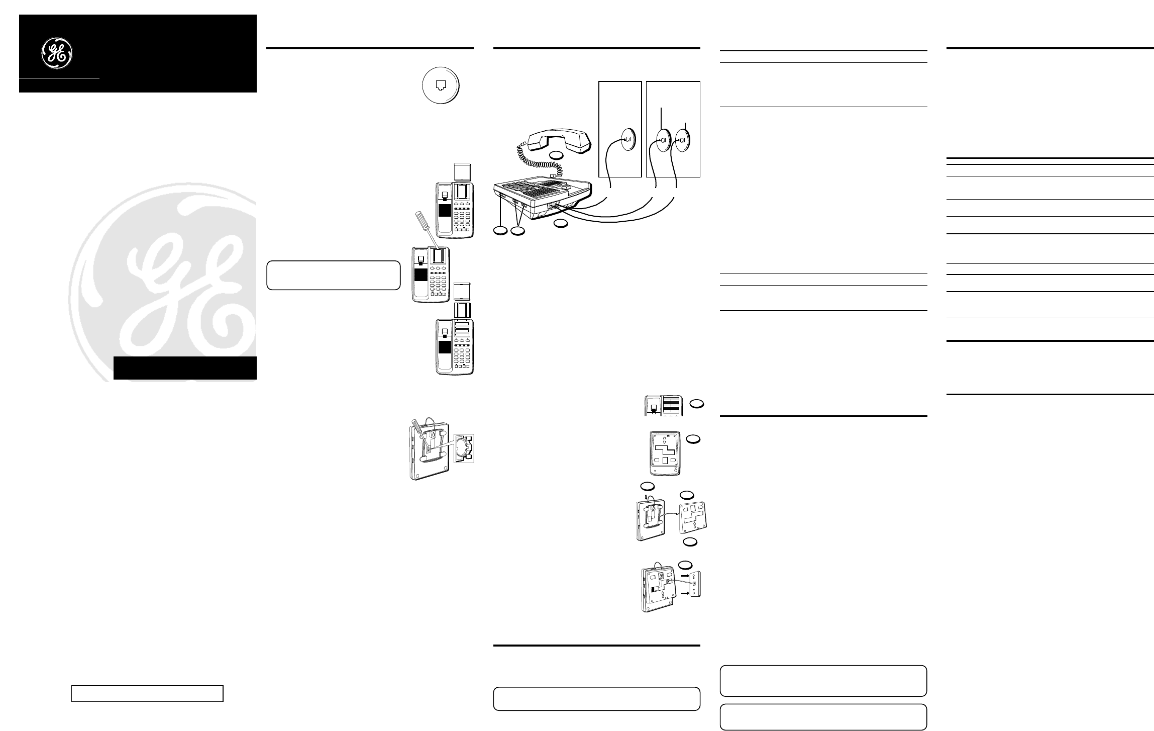
1. (See Figure 1) If you have one dual-line phone jack (RJ14C).
Plug the white straight cord in the LINE 1+2 jack at the top of the base.
Plug the opposite end of the cord into the modular RJ14C dual-line jack.
(See Figure 2) or if you have two single-line phone jack (RJ11C).
Plug the grey straight cord in the LINE 1+2 jack at the top of the base.
Plug the white straight cord into the LINE 2 jack.
Then, plug the opposite end of the cords into the modular RJ11C jacks.
2. Plug one end of the coiled handset cord into the handset and the opposite
end into the base.
3. Set the RINGER 1 and RINGER 2 volume switches to HI, LO or OFF.
Note in OFF position that line will not ring. Your telephone has separate
and distinct ringer sounds for each line this will allow you to determine
(audibly) the line of an incoming call.
4. Set mode switch to TONE. Note that if you have problems dialing switch to
PULSE.
WALL MOUNT INSTALLATION
1. Slide handset hook up and off the base. Turn
(half turn 180º) and slide back into place.
2. Press down and out on the two snap tabs
located on the top of the adapter. Lift adapter off.
3. Plug white straight line cord into base jack LINE
1+2 and wrap excess cord. Note that you must
use a RJ14C jack.
4. Reverse the adapter so that the thickest part is
at the bottom of the base. Place about 3” of the
cord through the opening in the adapter.
5. Replace the adapter by inserting the top end in
first and slide the base down.
6. Connect to the RJ14C wall jack and position
adapter mounting holes over the wall plate and
slide down until adapter/base assembly is firmly
in place.
7. Plug one end of the coiled handset cord into the
handset and the opposite end into the base.
8. Set the RINGER 1 and RINGER 2 volume switches
to HI, LO or OFF. Note in OFF position that line will
not ring. Your telephone has separate and
distinct ringer sounds for each line this will allow
you to determine (audibly) the line of an incoming
call.
9. Set mode switch to TONE. Note that if you have
problems dialing switch to PULSE.
REDIAL
Use REDIAL, to quickly redial the last number that was manually dialed. This
is useful when a line is busy for a long time.
1. Pick up the handset.
2. Wait for dial tone.
3. Press the REDIAL button. The phone automatically redials the last number
that was dialed (up to 16 digits).
FLASH BUTTON
Press the FLASH button to activate custom calling services such as call
waiting or call transfer, which are provided by your local phone company. Do
not use the hook switch because you might hang up the phone.
CONFERENCE BUTTON
Enables you to carry on three-way conversation using LINES 1 and 2 simultaneously.
1. Place first party on HOLD.
2. Press the alternate LINE.
3. Dial phone number for second party.
4. Press CONF and talk to both parties.
5. When finished with conference press LINE 1 or 2 to talk privately and
disconnect other line.
6. When finish hang up.
MEMORY
Each of the 12 memory buttons is capable of storing phone numbers that are
up to 16 digits. Each one–touch button accesses a memory position. You can
dial the phone numbers stored in the memory with one touch (press the
memory location button).
STORING A NUMBER IN MEMORY
1. Pick up the handset.
2. Press the STORE/IN button.
3. Dial the number to be stored (up to 15 digits).
4. Press STORE/IN again.
5. Press a memory location button (A, B, C, or 1-9).
6. Remove the memory directory from underneath its plastic cover and
record the name of the person whose number you stored.
7. Hang up the handset.
INSERTING A PAUSE IN THE DIALING SEQUENCE
Press the REDIAL button to insert a delay in the dialing sequence of a stored
telephone number when a pause is needed to wait for a dial tone (for example
after you dial 9 for an outside line, or to wait for a computer access tone).
Each pause counts as 1 digit in the dialing sequence.
CHANGING A STORED NUMBER
To change a stored number, you just replace it with a different number using
the procedure for storing a number.
DIALING A STORED NUMBER
1. Pick up the handset, and wait for a dial tone.
2. Press desired MEMORY button (A, B, C, or 1-9).
CAUTION: If you make test calls to emergency numbers, remain on the line
and explain the reason for the call to the dispatcher. Also, make these calls in
off-peak hours, such as early morning or late evening.
NOTE: If you make a mistake while storing a number, hang up and repeat
the storing procedure.
TROUBLESHOOTING TIPS
Problem Solution
No dial tone. • Check hook switch to make sure it pops up.
Won't dial out • Make sure TONE/PULSE is set to correct position.
• Check if a LINE button depressed.
Phone doesn’t ring • Check RINGER VOLUME.
• You might have too many phones on one line.
Light and tone fluctuating with • This is normal as power is feedback flutter when
phone outpulsing. dialing in pulse mode.
Can’t be heard by • Make sure phone cord is securely plugged in.
other party • Make sure other phones are not OFF hook at the
same time. If so, this is normal condition as volume
drops when additional phones are used at once.
Memory dialing
• Make sure you entered numbers correctly. (See “Memory.”)
Memory Loss • Is Lithium battery installed correctly.
• Does battery need replaced.
Indicator lights do not • Check all of the phones on this line.
Turn on or off properly • Check the “AA” batteries.
• Switch the line cord jacks for lines 1 and 2.
At this phone From another phone
1. Pick up handset.
2. Press LINE on hold.
1. Pick up handset.
TO CONTINUE THE CONVERSATION
HOLD BUTTON
• Press HOLD button and hang up the handset. The LINE indicator blinks to
indicate the party is on hold.
NOTE: You can use the telephone if you have only one incoming line. However
you cannot access a second line. Also see” Batteries for Supplementary Power”.
1
2
3
4
5
6
We bring good things to life.
BEFORE YOU BEGIN
MODULAR JACK REQUIREMENTS
You need an RJ11C or RJ14C type modular jack,
which is the most common type of phone jack and
might look like the one pictured here. If you don’t
have a modular jack, call your local phone company
to find out how to get one installed.
INSTALLATION
MAKING AND RECEIVING CALLS
To Make a Call To Receive a Call
1. Press LINE 1 or LINE 2.
2. Replace the handset to hang up.
1. When phone rings (LINE indicator
flashes rapidly).
1. Press LINE 1 or LINE 2.
2. Pick up the handset to answer.
3. Replace the handset to hang up.
GENERAL PRODUCT CARE
To keep your Telephone working and looking good, follow these guidelines:
• Avoid putting it near heating appliances and devices that generate
electrical noise (for example, motors or fluorescent lamps).
• DO NOT expose to direct sunlight or moisture.
• Avoid dropping the unit and/or other rough treatment.
• Clean with a soft cloth.
• Never use a strong cleaning agent or abrasive powder because this will
damage the finish.
• Retain the original packaging in case you need to ship it at a later date.
LIMITED WARRANTY
What your warranty covers:
• Any defect in materials or workmanship.
For how long after your purchase:
• One year.
(The warranty period for rental units begins with the first rental or 45 days from date of
shipment to the rental firm, whichever comes first.)
What we will do:
• Provide you with a new or, at our option, a refurbished unit.
• The exchange unit is under warranty for the remainder of the original product’s warranty
period.
How to make a warranty claim:
• Properly pack your unit. Include any cables, etc., which were originally provided with the
product. We recommend using the original carton and packing materials.
• Include in the package evidence of purchase date such as the bill of sale. Also print your
name and address and a description of the defect. Send standard UPS or its equivalent to:
Thomson Consumer Electronics, Inc.
Product Exchange Center
32 Spur Drive
El Paso, Texas 79906
• Pay any charges billed to you by the Exchange Center for service not covered by the warranty.
• Insure your shipment in case of loss or damage. Thomson accepts no liability in case of
damage or loss.
• A new or refurbished unit will be shipped to you prepaid freight.
What your warranty does not cover:
• Customer instruction. (Your Owner’s Manual provides information regarding operating
instructions and user controls. For additional information, ask your dealer.)
• Installation and set-up service adjustments.
• Batteries.
• Damage from misuse or neglect.
• Products which have been modified or incorporated into other products.
• Products purchased or serviced outside the USA.
• Acts of God, such as but not limited to lightning damage.
Product Registration:
• Please complete and mail the Product Registration Card packed with your unit. It will make it
easier to contact you should it ever be necessary. The return of the card is not required for
warranty coverage.
How state law relates to this warranty:
• This warranty gives you specific legal rights, and you may have other rights which vary from
state to state.
If you purchased your product outside the USA:
• This warranty does not apply. Contact your dealer for warranty information.
ACCESSORY ORDERING INFORMATION
Please call 1-800-338-0376 Monday through Friday between 8 AM and 8 PM to
order a lithium battery cartridge (part number 5-1923; price $2.95 plus $5.00 for
shipping and handling).
FCC NUMBER IS LOCATED ON THE CABINET BOTTOM
REN NUMBER IS LOCATED ON THE CABINET BOTTOM
FIGURE 1.
FIGURE 2.
One dual-line jack
Two single-line jacks
Cord from
LINE 1+2 jack
Cord from
LINE 1+2 jack
Cord from
LINE 2 jack
1
3
4
WHITE
WHITEGRAY
(RJ14C)
(RJ11C)
(RJ11C)
2


