


Installing the Phone
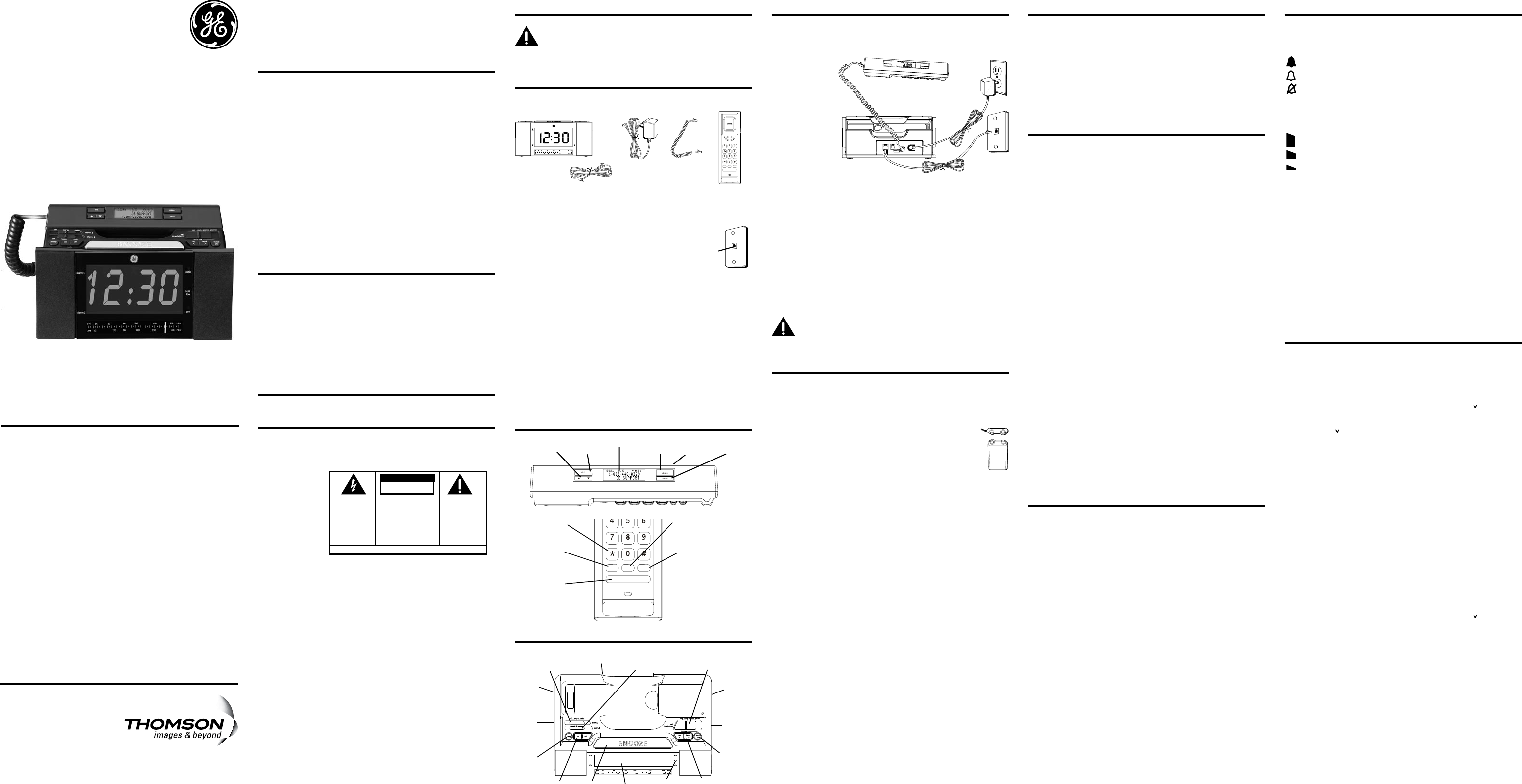
Connecting the Telephone Line
Choose the best location to install your telephone. Your telephone
should be placed on a level surface, such as a desk or table top.
1. Plug one end
of the straight
telephone line
cord into the
PHONE LINE
jack on the
base.
2. Plug the other
end into a wall
jack.
3. Plug one end
of the coiled
handset cord into the jack on the handset.
4. Plug the other end into the HANDSET jack on the back of the base.
5. Place the handset on the base cradle.
6. Set the RINGER and DISPLAY BRIGHTNESS switches on the back of
the base to the desired settings.
7. Set the VOL switch on the side of the handset to the desired
setting.
Connecting the Electrical Power
1. Plug one end of the power supply cord into the back of the base.
2. Plug the other end into an electrical outlet.
CAUTION: To reduce risk of personal injury, re, or
damage use only the 5-2836 power adaptor listed in
the user’s guide. This power adaptor is intended to be
correctly orientated in a vertical or oor mount position.
“No Worry” Battery Backup
This telephone is equipped with a memory holding system
powered by a customer-installed 9-volt alkaline battery
(not included).
When electrical power is interrupted, or the electrical line is
unplugged, the battery operates the clock to
retain the time of day and alarm settings in
memory. When the unit is running on battery
power, the digital display does not light up;
however, if wake time occurs during the power
interruption, the alarm buzzer sounds (regardless
of the type of alarm tone selected) if remaining battery power is
adequate. Normal operation resumes after electrical power is
restored.
NOTE: The battery power indicator illuminates if the
battery power level is low or if no battery is installed.
Please replace/install the batteries as soon as
possible in order to maintain Caller ID operation.
Install the backup battery as follows:
1. Remove the battery compartment cover located on the bottom of
the base.
2. Connect a fresh 9-volt alkaline battery (not included). Interlock the
large and small contacts on the battery clip and the battery. Once
connected, place the battery inside the battery compartment.
3. Replace the battery compartment cover.
NOTE: 9V Alkaline (NEDA 1604A) batteries are
recommended.
NOTE: If battery is not installed:
a) All memory will be lost if the unit is unplugged for
more than 60 seconds.
b) The clock will stop running during a power outage
period but will start running when power resumes.
The clock will blink to indicate that the time may not
be correct.
IMPORTANT: If storing this unit for more than 30
days, remove the battery.
Important Information
NOTICE: This product meets the applicable Industry Canada technical
specications.
The equipment must be installed using an acceptable method of
connection. The customer should be aware that compliance with the
above conditions may not prevent degradation of service in some
situations.
Repairs to certied equipment should be made by an authorized
Canadian maintenance facility designated by the supplier. Any repairs
or alterations made by the user to this equipment, or equipment
malfunctions, may give the telecommunications company cause to
request the user to disconnect the equipment.
Users should ensure for their own protection that the electrical
ground connections of the power utility, telephone lines and internal
metallic water pipe systems, if present, are connected together. This
precaution may be particularly important in rural areas.
CAUTION: Users should not attempt to make such connections
themselves, but should contact the appropriate electric inspection
authority, or electrician, as appropriate.
NOTES: This equipment may not be used on coin service provided by
the telephone company.
Interference Information
This equipment generates and uses radio frequency energy which
may interfere with residential radio and television reception if not
properly installed and used in accordance with instructions contained
in this manual. Reasonable protection against such interference is
ensured, although there is no guarantee this will not occur in a given
installation. If interference is suspected and veried by switching
this equipment on and off, the user is encouraged to try to correct
the interference by one or more of the following measures: Reorient
the radio/television receiver’s antenna, relocate the equipment with
respect to the receiver, plug the equipment and receiver into separate
circuit outlets. The user may also wish to consult a qualied radio/
television technician for additional suggestions. This equipment has
been fully tested and complies with all limits for Class B computing
devices pursuant to part 15 FCC Rules and Regulations. This device
complies with RSS-210 of Industry Canada. Operation is subject to the
following two conditions: (1) This device may not cause interference,
and (2) This device must accept any interference, including
interference that may cause undesired operation of the device.
REN Number
On the bottom of this equipment is a label indicating, among other
information, the Ringer Equivalence Number (REN) for the equipment.
The REN is useful in determining the number of devices you may
connect to your telephone line and still have all of these devices ring
when your telephone number is called. In most (but not all) areas,
the sum of the RENs of all devices connected to one line should not
exceed 5. To be certain of the number of devices you may connect
to your line as determined by the REN, you should contact your local
telephone company.
REN Number is located on the cabinet bottom.
Licensing
Licensed under US Patent 6,427,009.
Hearing Aid Compatibility (HAC)
This telephone system meets FCC/Industry Canada standards for
Hearing Aid Compatibility.
Base Operation
Setting the Clock
1. Slide the set time /alarm switch to clock. The screen ashes the
setting time.
2. Press the
<rev/fwrd> or fwrd >> button to set the clock time.
3. Slide the
set time/alarm switch to lock. The screen displays the
current time.
Display Backlight
Use the brightness switch to select the desired setting: high or low.
Alarm Operation
The 29298 is equipped with two alarms. The alarms can be set
independently to either radio or buzzer.
Setting the Alarm Time
1. Slide the set time /alarm switch to alarm 1 or alarm 2. The
corresponding alarm time will be shown on the clock display.
2. Press the
<rev/fwrd> or fwrd >> button to set the alarm time.
Set Alarm Tone
1. Slide the alarm 1 or alarm 2 switch to choose radio, buzzer or off.
2. The corresponding alarm ON indicator on the display illuminates.
Turning Off the Alarms
1. To turn off the alarm, press the off side of the radio on/off button
once. Alarm is still active and will be delivered when alarm time is
reached again. Alarm ON indicator remains illuminated.
2. Alarm is de-activated by sliding the
alarm 1 or alarm 2 switch
to OFF.
Snooze Timer
After the wake mode is activated, you can silence for 6 minutes by
pressing the SNOOZE button.
You may use the snooze feature repeatedly.
Using the Sleep Timer
Use the sleep timer to play the radio up to 59 minutes and then have it
shut off automatically.
1. Press the
sleep button once to activate the radio sleep timer.
2. The timer can be adjusted from 59 minutes to 1 minute.
3. To set sleep time, press and hold the
sleep button. The time shown on
the clock display will decrease. Then release the sleep button when the
desired length of time is shown on the clock display.
4. Press the
off button to de-activate the sleep function.
Radio Operation
1. Press the on side of the radio on/off button to turn the radio on.
2. Slide the
AM/FM switch to select the desired broadcast band.
3. Rotate the
radio channel tuning knob to select a radio station /
frequency.
4. Rotate the
volume -/+ control knob to adjust the listening level.
5. To turn the radio off, press the
off side of the radio on/off button.
NOTE: You can also turn on the radio after lifting
up the handset by pressing the on side of the radio
on/off button.
NOTE:
The Radio broadcast will automatically turn
off when you picked up the handset. Broadcast will
resume when you replace the handset on cradle.
AM Antenna
A built-in antenna eliminates the need for an outside antenna for AM
reception. Moving the unit slightly may improve reception of distant
AM signals.
FM Antenna
The power cord acts as your FM antenna. The power cord picks up
moderate to strong signals and eliminates the need for an external
antenna in most strong signal areas. Be sure the power cord is
stretched to its longest length. Do not coil or bunch the cord together.
Changing position of the power cord may improve reception.
Telephone Operation
Adjusting the Ringer Volume
You may control the ringer volume level with the switch located on the
side of the base.
= loud
= low
= off
Handset Receiver Volume
Use the VOLUME switch on the rear of the handset to adjust the
handset receiver volume.
= high
= mid
= low
Flash
Press the ash button to activate customer calling services,
such as call transfer, which are services provided by your local
phone company.
Redial
To redial the last number called (up to 32 digits), use the redial feature.
1. Pick up the handset.
2. Press the
redial button.
3. The last number is automatically redialed.
Using One Touch Redial
If the last call you dialed was busy, you can redial it immediately by
just pressing the redial button and without hanging up the handset.
Setting Up the Caller ID Menu
IMPORTANT: Do not plug the telephone into the wall
jack while setting up the Caller ID menu because an
incoming call may invalidate the information not yet
saved.
1. Place the handset in the cradle on the base.
2. Press the
menu button. the screen displays SET ^ OR .
3. Press the
CID5 or 6 button to scroll among the 7 menu screens;
•
SET ^ OR
• Local Area Code (default ” - - -”)
•
Regional AC’s-1 (default “- - - - - - - - -”)
•
CID LANGUAGE (default English)
•
SELECT CONTRAST (default 3)
•
T/P DIAL MODE (default tone)
•
EXIT SETUP
NOTE: You may press the dial button anytime to exit
the Caller ID Set Up menu. If no buttons are pressed
within 10 seconds, the phone automatically exits the
Caller ID Set Up menu and returns to the NO CALLS
summary screen.
Local Area Code
The telephone uses the programmed area code to determine the
number format to display when a valid Caller ID signal is received. It is
also used for the Dialback feature.
1. Press the
menu button. the screen displays SET ^ OR .
2. Press the
CID5 or 6button until the screen displays LOCAL AREA
CODE, The default setting is ”_ _ _” .
3. To enter or change the area code, press the menu button. The
screen displays the area code stored in memory. The left-most digit,
or a minus sign (-) ashes, indicating the unit is ready to accept the
area code entry.
4. Press the
CID 6 button to select a number from 0-9 in ascending
order. Or press the CID 5 button to select numbers from 9-0 in
descending order.
5. Press the
menu button to advance to the next digit.
6. After the 3rd and last digit is entered, press the
menu button to
store the area code and go to the next setting.
NOTE: If you make a mistake, you can simply repeat
the previous steps until your area code is set.
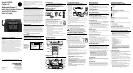
Model 29298
Caller ID
BedroomPhone™
with Dual-Wake Alarms
and AM/FM Radio
User’s Guide
Visit the GE website at: www.GE.com/phones
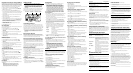
Handset
Base
AC power
adaptor
Telephone line
cord
Handset
cord
store mem redial
flash
tone
oper
pqrs wxyz
tuv
ghi mno
jkl
def
abc
store mem redial
flash
tone
oper
pqrs wxyz
tuv
ghi mno
jkl
def
abc
CID
5
or
6
(Caller ID
button)
dial
(button)
delete
(button)
menu
(button)
display
*/tone
(button)
redial
(button)
mem
(memory
button)
store
(button)
ash
(button)
VOLUME
(switch)
< rev/fwrd>
(reverse/forward
button)
sleep
(button)
alarm 2
off/buzzer/radio
(switch)
AM/FM
(switch)
set time/alarm
(switch)
radio on/off
(button)
volume
-/+
control
knob
radio
channel
tuning
knob
SNOOZE
(button)
alarm 1
off/buzzer/radio
(switch)
brightness
(switch)
fwrd>>
(fast forward
button)
display
ringer
(switch)
battery
power
indicator
SEE MARKING ON BOTTOM / BACK OF PRODUCT
RISK OF ELECTRIC SHOCK
DO NOT OPEN
WARNING: TO
PREVENT FIRE OR
ELECTRICAL SHOCK
HAZARD, DO NOT
EXPOSE THIS
PRODUCT TO RAIN
OR MOISTURE.
THE LIGHTNING
FLASH AND ARROW
HEAD WITHIN THE
TRIANGLE IS A
WARNING SIGN
ALERTING YOU OF
“DANGEROUS
VOLTAGE” INSIDE
THE PRODUCT.
CAUTION: TO REDUCE THE
RISK OF ELECTRIC SHOCK, DO
NOT REMOVE COVER (OR
BACK). NO USER
SERVICEABLE PARTS INSIDE.
REFER SERVICING TO
QUALIFIED SERVICE
PERSONNEL.
THE EXCLAMATION
POINT WITHIN THE
TRIANGLE IS A
WARNING SIGN
ALERTING YOU OF
IMPORTANT
INSTRUCTIONS
ACCOMPANYING
THE PRODUCT.
CAUTION:
Model 29298
00023808 (Rev. 0 CAN E)
08-17
Printed in China
Thomson Multimedia Ltd.
30 Eglinton Ave W., Suite 304
Mississauga, ON Canada L5R 3E7
© 2008 Thomson Multimedia Ltd.
Trademark(s) ® Registered
Marque(s) ® déposée(s)
Modular
telephone
line jack
Wall plate
Introduction
CAUTION: When using telephone equipment,
there are basic safety instructions that should
always be followed. Refer to the IMPORTANT
SAFETY INSTRUCTIONS provided with this product
and save them for future reference.
Before You Begin
Parts Checklist
Make sure your package includes the following items:
Telephone Jack Requirements
To use this phone, you need an RJ11C type
modular telephone jack, which might look like
the one pictured here, installed in your home. If
you don’t have a modular jack, call your local
phone company to nd out how to get one
installed.
Important Installation Guidelines
• Install telephone near both a telephone (modular) jack and an
electrical power outlet.
• Avoid sources of noise, such as a window by a busy street,
and electrical noise, such motors, microwave ovens, and
uorescent lighting.
• Avoid heat sources, such as heating air ducts, heating
appliances, radiators, and direct sunlight.
• Avoid areas of excessive moisture or extremely low temperature.
• Avoid dusty locations.
• Avoid other cordless telephones or personal computers.
Handset Layout
-
-
+
+
Battery clip
Battery
Type
NEDA
1604A
9V
Base Layout