


3-21
Cisco Wireless LAN Controller Configuration Guide
OL-8335-02
Chapter 3 Configuring Ports and Interfaces
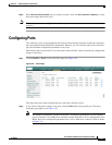
Configuring Ports
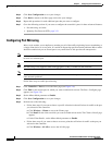
b. Click Detail for the access point on which you want to enable mirror mode. The All APs > Details
page appears.
c. Under General, set the Mirror Mode parameter to Enable.
Step 6 Click Save Configuration to save your changes.
Configuring Spanning Tree Protocol
Spanning Tree Protocol (STP) is a Layer 2 link management protocol that provides path redundancy
while preventing loops in the network. For a Layer 2 Ethernet network to function properly, only one
active path can exist between any two network devices. STP allows only one active path at a time
between network devices but establishes redundant links as a backup if the initial link should fail.
The spanning-tree algorithm calculates the best loop-free path throughout a Layer 2 network.
Infrastructure devices such as controllers and switches send and receive spanning-tree frames, called
bridge protocol data units (BPDUs), at regular intervals. The devices do not forward these frames but
use them to construct a loop-free path.
Multiple active paths among end stations cause loops in the network. If a loop exists in the network, end
stations might receive duplicate messages. Infrastructure devices might also learn end-station MAC
addresses on multiple Layer 2 interfaces. These conditions result in an unstable network.
STP defines a tree with a root bridge and a loop-free path from the root to all infrastructure devices in
the Layer 2 network.
Note STP discussions use the term root to describe two concepts: the controller on the network that serves as
a central point in the spanning tree is called the root bridge, and the port on each controller that provides
the most efficient path to the root bridge is called the root port. The root bridge in the spanning tree is
called the spanning-tree root.
STP forces redundant data paths into a standby (blocked) state. If a network segment in the spanning tree
fails and a redundant path exists, the spanning-tree algorithm recalculates the spanning-tree topology
and activates the standby path.
When two ports on a controller are part of a loop, the spanning-tree port priority and path cost settings
determine which port is put in the forwarding state and which is put in the blocking state. The port
priority value represents the location of a port in the network topology and how well it is located to pass
traffic. The path cost value represents media speed.
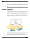
The controller maintains a separate spanning-tree instance for each active VLAN configured on it. A
bridge ID, consisting of the bridge priority and the controller’s MAC address, is associated with each
instance. For each VLAN, the controller with the lowest controller ID becomes the spanning-tree root
for that VLAN.
STP is disabled for the controller’s distribution system ports by default. The following sections provide
instructions for configuring STP for your controller using either the GUI or CLI.