


7-5
Cisco Wireless LAN Controller Configuration Guide
OL-8335-02
Chapter 7 Controlling Lightweight Access Points
Lightweight Access Point Overview
Note that the wireless LAN operator can disable either one of each pair of the Cisco 1000 series
lightweight access point internal antennas to produce a 180-degree sectorized coverage area. This feature
can be useful, for instance, for outside-wall mounting locations where coverage is only desired inside
the building, and in a back-to-back arrangement that can allow twice as many clients in a given area.
Refer to Appendix E, “Antenna Patterns for 1000 Series Access Points” for antenna patterns.
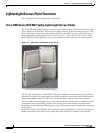
External Antenna Connectors
The AP1020 and AP1030 Cisco 1000 series lightweight access points have male reverse-polarity TNC
jacks for installations requiring factory-supplied external directional or high-gain antennas. The external
antenna option can create more flexibility in Cisco 1000 series lightweight access point antenna
placement.
Note The AP1010 Cisco 1000 Series lightweight access points are designed to be used exclusively with the
internal high-gain antennas, and have no jacks for external antennas.
Note that the 802.11b/g 2.4 GHz Left external antenna connector is associated with the internal Side A
antenna, and that the 2.4 GHz Right external antenna connector is associated with the internal Side B
antenna. When you have 802.11b/g diversity enabled, the Left external or Side A internal antennas are
diverse from the Right external or Side B internal antennas.
Also note that the 802.11a 5 GHz Left external antenna connector is separate from the internal antennas,
and adds diversity to the 802.11a transmit and receive path. Note that no external 802.11a antennas are
certified in FCC-regulated areas, but external 802.11a antennas may be certified for use in other
countries.
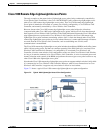
Antenna Sectorization
Note that the Cisco WLAN Solution supports Antenna Sectorization, which can be used to increase the
number of clients and/or client throughput a given air space. Installers can mount two Cisco 1000 series
lightweight access points back-to-back, and the Network operator can disable the second antenna in both
access points to create a 360-degree coverage area with two sectors.
Installers can also mount Cisco 1000 series lightweight access points on the periphery of a building and
disable the Side B internal antennas. This configuration can be used to supply service to the building
interior without extending coverage to the parking lot, at the cost of eliminating the internal antenna
diversity function.
Refer to Appendix E: Internal Antenna Patterns for information on the radiation patterns of internal
antennas in 1000 series lightweight access points.
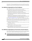
Cisco 1000 Series Lightweight Access Point LEDs
Each Cisco 1000 series lightweight access point is equipped with four LEDs across the top of the case.
They can be viewed from nearly any angle. The LEDs indicate power and fault status, 2.4 GHz
(802.11b/g) Cisco Radio activity, and 5 GHz (802.11a) Cisco Radio activity.
This LED display allows the wireless LAN manager to quickly monitor the Cisco 1000 series
lightweight access point status. For more detailed troubleshooting instructions, refer to the Error
Messages and Access Point LEDs appendix.