


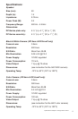
Specifications:
Speaker:
Size (mm): 50
Depth (in): 1.5
Impedance: 8 Ohms
Power Peak (W): 0.2
Frequency Range: 500 Hz - 4.5 kHz
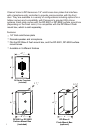
Dimensions:
3 1
DP-Series plate only: 6 ½” (L) x 4 / ” (W) x / ” (D)
8 4
3 3
DP-Series assembly: 6 ½” (L) x 4 / ” (W) x 1 / ” (D)
8 4
Black & White Camera: (DP-5xxx & DP-5xxxP only)
Camera Lens: 3.8mm
Resolution: 500 lines
S/N Ratio: More than 48 dB
Min Illumination: 0.05 LUX @ F2.0
Power Supply: 12VDC regulated
Power Consumption: 110 mA
Video Output: 1 Vp-p @ 75 ohms
Dimensions: (see instruction for the 5401 B/W camera)
Operating Temp: -10°C to 50°C (14°F to 122°F)
Color Camera: (DP-6xxx & DP-6xxxP only)
Camera Lens: 3.8mm
Resolution: 380 lines
S/N Ratio: More than 48 dB
Min Illumination: 0.4 LUX @ F2.0
Power Supply: 12VDC regulated
Power Consumption: 120 mA
Video Output: 1 Vp-p @ 75 ohms
Dimensions: (see instruction for the 6401 color camera)
Operating Temp: -10°C to 50°C (14°F to 122°F)
Specifications subject to change without notice.
DP-xxxxC
500ft.
max
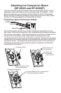
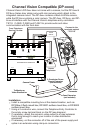
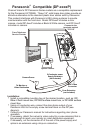
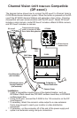
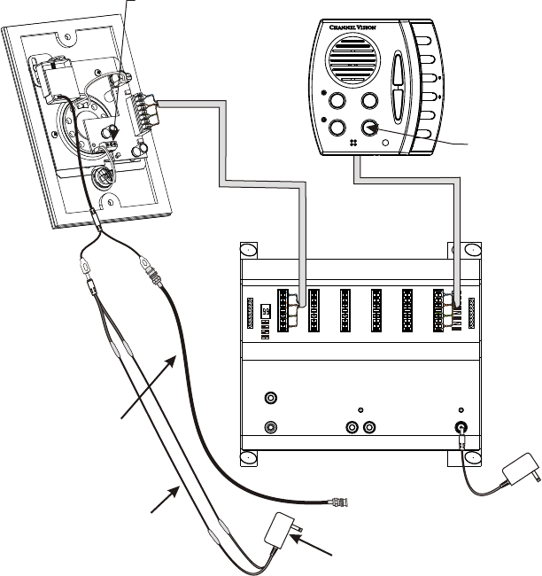
The diagram below shows how to connect the DP-xxxxC to Channel Vision’s
CAT5 Whole-House Intercom system. When the button is pressed on the DP-
xxxxC the ST-2000 Intercom Stations will generate a door chime. Pressing
Answer/End will open communication with the DP-xxxxC. Model DP-6xxxC
includes a color camera, model DP-5xxxC includes a Black & White camera,
and DP-0xxxC includes no camera.
Channel Vision Compatible
(DP-xxxx )
CAT5 Intercom
C
P-0930
PRO
CHANNEL
TM
VISION
CHANNEL
VISION
TM
Model
P-0930
Whole-House Intercom
Page Out
Page Trigger
IR
Emitters
+15VDC
Power
Link
In
Link
Out
Hub
A
B
C
D
Room 1 Room 2
Room 3
Room 4 Room 5
Room 6
ST-2000
Press here to
answer door
These terminals can be
used to connect a C5IDS
Door Strike Relay Module
Room 1
Room 2
Room 3
Room 4
Room 5
Room 6
Monitor
DND Answer/End
Page
Camera Power
To Monitor or
Video Distribution
Coax Extension
(not included)
BNC Video
Connector
2-Conductor power
Supply Extension
(not included)
Installation:
Install a compatible mounting box at the desired location, such as:
h
Using CAT5 wire, connect the P-0930 to the 110 connector on the DP
h
(see diagram).
If necessary, attach the camera’s video output to a coax extension
h
that is long enough to reach your monitor or video distribution
equipment.
If necessary, cut the connector off of the end of the power supply and
h
splice in an extension using crimp-on connectors.
DP-Rbox-II flush mount box, DP-9001 surface mount box, or DP-9002
surface mount box.
10
11