


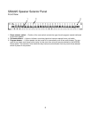
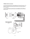

Speakers and Speaker Wiring
The MCP35A control panel of the SI and PI products is designed to use 25-volt distributed speakers. These
speakers have line-matching transformers with various power level taps. 8-ohm speakers or speakers without
line-matching transformers cannot be used with the SI and PI products.
Distributed speakers can be tapped at various power levels and this is determined by which wire from the
speaker’s transformer is used for connection. The user must determine which power tap gives acceptable vol-
ume in a given location. However, it is best to tap the speakers at the lowest acceptable power tap in order to
ensure that enough speakers can be connected to the system without overloading the system amplifier.
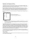
The chart below shows the wire colors and power taps for the T725 transformers used in all Bogen distributed
speakers.
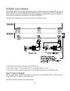
Caution
Do not attempt to connect a 25V speaker directly to the MCP35A, using GND as one of the connecting
points. This could seriously damage the MCP35A because the unit uses a balanced output when con-
nected to the speakers lines.
The MCP35A control panel of the PI and SI contains an internal amplifier with 35W power handling capability.
Therefore, the combined power of all the system speakers cannot exceed 35W. To determine the required
power that the system amplifier must handle, add up all the power taps selected for all the speakers in the sys-
tem. This is the total system power requirement. If the total of the speaker power taps is too high for the sys-
tem to handle, it may be necessary to tap the speakers at the next lowest setting in order to keep from overload-
ing the amplifier. In many instances, the required speaker tap setting will be either 1/4 or 1/2 watt (you should
also factor in 20% additional power loss through wires, transformers, etc. as a safety margin). The MCP35A’s
35-watt amplifier should provide sufficient power for most applications.
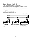
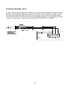
If the system’s power requirements are greater than 35 watts and cannot be lowered, it may be necessary to
use an external booster amp. The booster amp replaces the internal amplifier of the MCP35A. Booster amp con-
nections are described later in this manual.
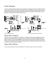
Time Tones
A tone signal sounds through all speakers when the clock terminal is grounded through a closure from a master
clock. Reference call out #6 on page 7.
12
T725
Leads 25V 70V
Black COM COM
Brown 4
Red 2
Orange 1
Yellow 1/2 4
Green 1/4 2
Blue 1/8 1
Violet 1/2
Gray 1/4
White 1/8
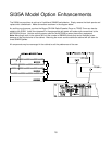
For SI35A and PI35A applications,
use the 25V column for speaker connections.