


GX2401c I/B version 09050A-1
09050A-1 10
OWNER’S MANUAL#GX2401c VER.09050A-1
PAGE:
10
English version
8
1 2
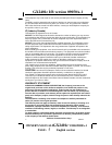
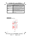
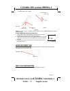
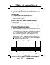
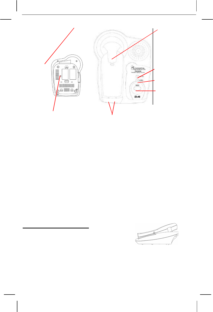
Bottom View
7
6
5
3 4
(Figure 2)
BASE UNIT CONTROLS
1. 9VDC Adapter Jack:
A
jack located on the rear side of the base unit used for
connecting the adapter to the base unit
.
2.
TEL LINE Jack:
Accepts line cord to make connection with modular type telephone
outlet.
3. T / P (TONE / PULSE) Switch:
Allows you to select the appropriate dialing service.
TONE for tone dialing or PULSE for rotary service.
4. Charge Terminals:
Used for charging the handset battery. We recommend that you
clean these contacts periodically with an alcohol-moistened cloth or cotton swab.
5. Page Button:
Allows you to locate the handset when it is not on the base.
6. IN USE / CHARGE LED Indicator:
Lights up steadily when the phone is in talk mode
and when the handset is being charged on the base. Turns off when the handset is not in
use and when the handset is removed from its cradle. Flashes when paging the handset.
7. NEW CALL LED Indicator:
Flashes if the system has new call message and have
message(s) in your voice mailbox (if you subscribe to your telephone company's voice
mail service).
8. Retainer Tab:
Allows the handset to hang on the base unit in the wall mount position
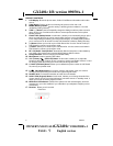
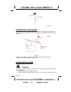
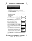
MOUNTING POSITION
DESKTOP USE:
Connect the telephone line cord to the TEL LINE jack on
the rear of the base unit and connect the opposite end to
the telephone modular jack.
(Figure 3)
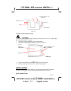
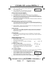
WALL USE :
A. WITH A STANDARD AT&T OR GTE MODULAR WALL JACK
1.
Install the wall mount bracket at the position as shown in Figure 4.
2.
Connect the short telephone line cord to the TEL LINE jack on rear of the base unit.
3. Connect the opposite end of the telephone line cord to the modular wall jack.
4.
Align the wall mounting slots with the studs located on the modular wall plate and slide