


The CT240 telephone controller is designed to remotely control your
home’s thermostat. It is possible to command a temperature
decrease (Unoccupied) during a prolonged absence or a temperature
increase (Comfort) before you return home.
Depending on your thermostat’s operating characteristics, it either
connects to the Aube output (for most Aube models) or to the auxil-
iary output.
When the auxiliary output is not used to control a thermostat, it can
be used to simultaneously control a load such as a water heater,
lighting, etc.
Any device connected to a telephone line must conform to the coun-
try's standards. The CT240 telephone controller meets:
• FCC68 standards for installation on the North American network.
• FDTBR21 standards for installation on the European network.
2.1 Included Parts
• One CT240 telephone controller
• One power transformer 120 V (North America) or 250 V (Europe)
• One 5 m (16 foot) telephone cable
NOTE: If you are using an answering machine, position the answer-
ing machine switch to ON before installing the CT240.
Make sure that your answering machine answers after a minimum of
4 rings.
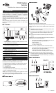
n Mount the CT240 near a telephone outlet.
NOTE: If you plan to connect a load having more that 30 volts on the
auxiliary output, the CT240 must be installed inside a certified electri-
cal box.
o OPTIONAL. Connect your phone (or answering machine) to the
PHONE connector of the CT240.
p Connect one end of the telephone cable to the LINE connector of
the CT240 and the other end to the telephone outlet in your
home.
q Connect the thermostat and load. Both outputs work simulta-
neously.
NOTE: Refer to your thermostat’s electrical specifications (telephone
interface) for the connection requirements.
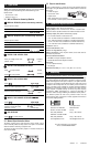
• If your thermostat requires a 12 VDC signal to switch to Vaca-
tion setpoint, use the ABC output (FIGURE 4):
A and C terminals:
• 0 VDC in Comfort mode
• 12 VDC in Vacation mode
NOTE: 50 mA max. for parallel connection of Aube thermostats.
• If your thermostat requires a dry contact to switch to the Vaca-
tion setpoint, use the 123 output (FIGURE 5):
• Load = terminals 2 and 3 (NC) (open = Vacation)
• Thermostat = terminals 1 and 2 (NO) (closed = Vacation)
r When all connections have been made, connect the power
transformer to the 9 V outlet of the CT240 and the other end to
the wall electrical outlet. The power indicator light is ON when
the circuit is powered.
1 . Introduction
1 Power Indicator. Indicates the CT240 is powered on. To turn
it off, unplug the power transformer.
2 Communication Indicator. Indicates the CT240 has
answered and is awaiting a command.
3 Ring Indicator. This indicator flashes when the phone rings.
4 Reset. This button can be used to reset the CT240 to its
default values. See section 3.3.
5 Manual Output Activation Button. Can be used to manually
switch the relay status.
6 Auxiliary Output. See section 2.
7 12 VDC Output. See section 2.
2. Installation
CT240 Telephone
Controller
Installation Instructions and User Manual
1/2 400-240-001-A