


61202076L1-1 TSU 600 User Manual v
List of Figures
Figure 1-1. TSU 600 Option Modules ................................................................... 1-4
Figure 1-2. Router, PBX, Video Conferencing Application Set Up .................. 1-5
Figure 1-3. Drop and Insert, Voice, and Router Application Set Up ............... 1-6
Figure 2-1a. TSU 600 Rear Panel ............................................................................ 2-5
Figure 2-1b. TSU 600 with DC Power Rear Panel............................................... 2-6
Figure 2-1c. TSU 600e Rear Panel.......................................................................... 2-7
Figure 2-1d. TSU 600e with DC Power Rear Panel............................................. 2-8
Figure 2-2. TSU 600 Interfaces ............................................................................... 2-9
Figure 2-3. TSU 600 Slot Designation (Rear View)........................................... 2-10
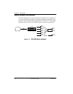
Figure 2-4. Example of Chain In.......................................................................... 2-13
Figure 3-1. TSU 600 Front Panel Layout .............................................................. 3-4
Figure 3-2. Example of Basic Front Panel Menu Travel..................................... 3-6
Figure 3-3. Display and Data Fields...................................................................... 3-8
Figure 3-4. Module Slots, TSU 600 ........................................................................ 3-9
Figure 4-1. Complete Status Menu........................................................................ 4-1
Figure 4-2. Network Interface Performance Report ........................................... 4-2
Figure 4-3. Display of Alarm Messages ............................................................... 4-4
Figure 5-1. Configuration Menu............................................................................ 5-1
Figure 5-2. Network Timed Clock Source............................................................ 5-4
Figure 5-3. DTE Timed Clock Source ................................................................... 5-5
Figure 5-4. Internal Clock Source.......................................................................... 5-6
Figure 5-5. Secondary Clock Source ..................................................................... 5-7
Figure 5-6. Normal (CSU)....................................................................................... 5-8
Figure 5-7. DS0 Map Designations...................................................................... 5-12
Figure 5-8. Create Temp Selection Screen.......................................................... 5-14
Figure 6-1. Utility Menu Tree ................................................................................ 6-1
Figure 7-1. Test Menu ............................................................................................. 7-1
Figure 7-2. Network Loopback Tests.................................................................... 7-3
Figure 8-1. Telnet/Terminal Main Menu............................................................. 8-1
Figure 8-2. DS0 Temp Map .................................................................................... 8-2
Figure 8-3. Unit Access Table ................................................................................ 8-6